Library Setup
Creating a new project
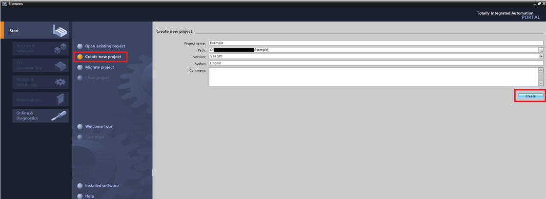
Step 1: In the start screen click Create new project. Choose a name and path for the project then click "Create"
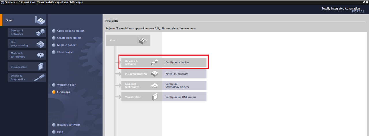
Step 2: In the First steps screen click "Configure a device"
Step 3: Then click "Add new device"
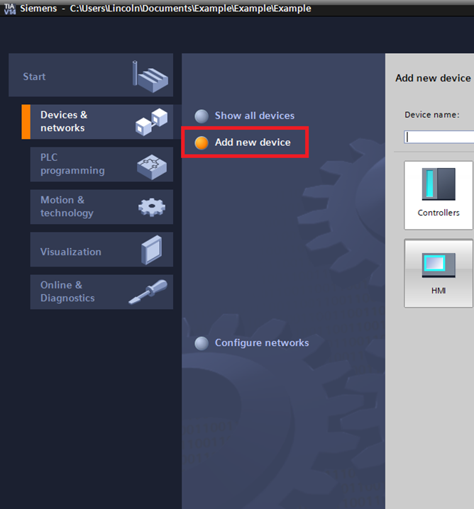
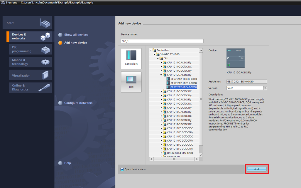
Step 4: In the add new device screen select the controller that is being used. This example uses a CPU 1212C AC/DC/Rly
Setup Fieldbus
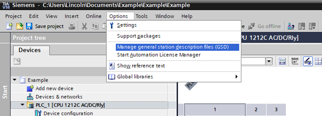
Step 1: Click Options->Manage general station description files (GSD)
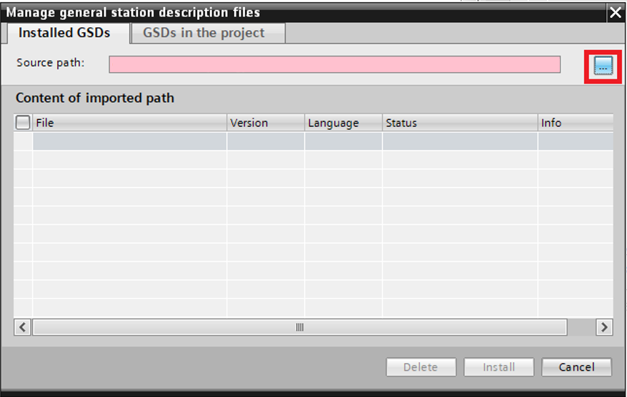
Step 2: In the Manage general station description files click "…"
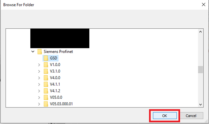
Step 3: In the Browse For Folder window browse to the folder that contains the included PMC GSD file
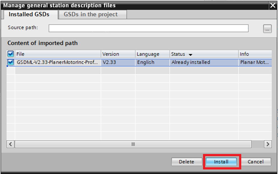
Step 4: Select the PMC GSD and then click "Install"
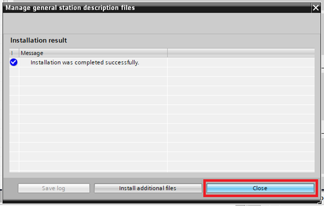
Step 5: Click "Close" in the confirmation window
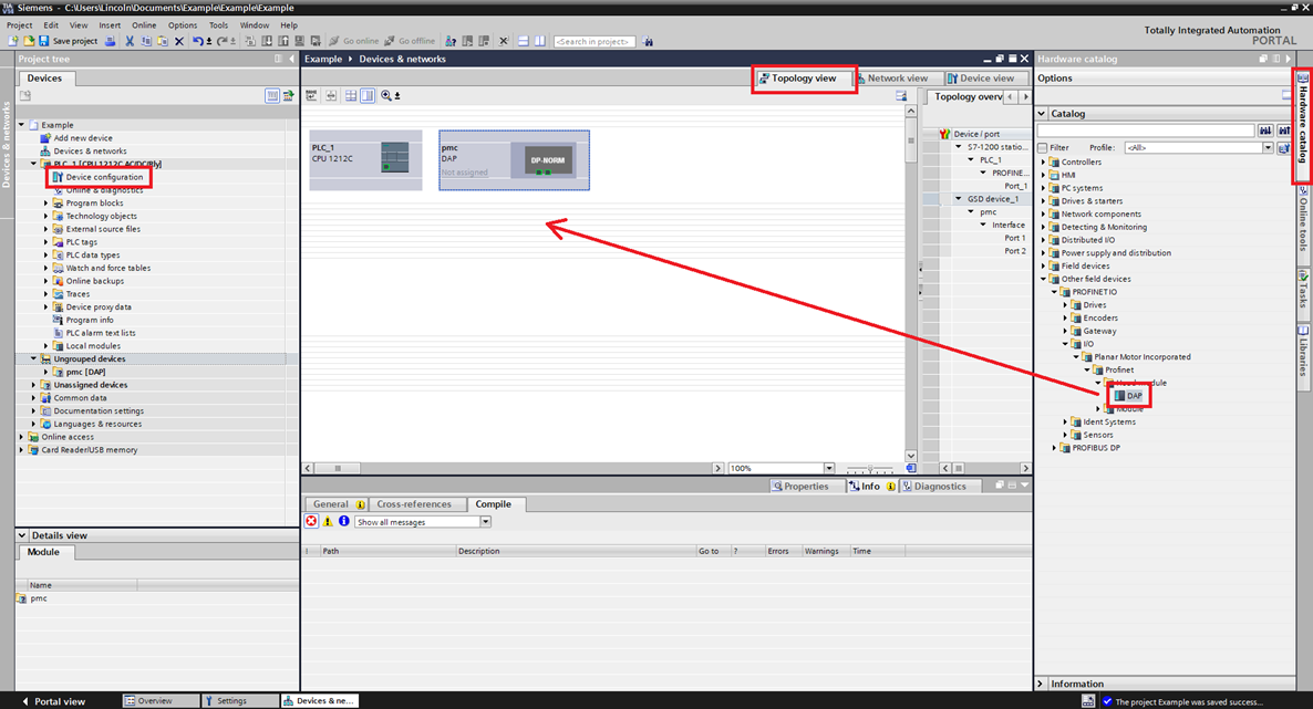
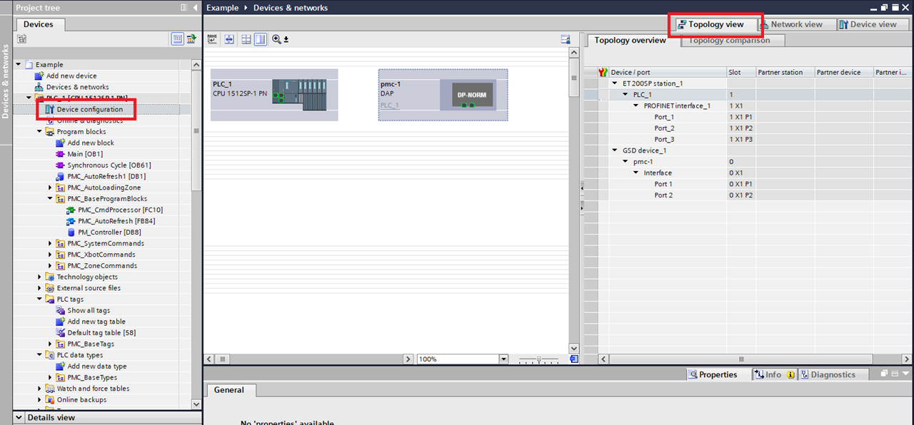
Step 6: Expand the PLC in the Project tree. Click Device configuration. In the Devices & networks window enter the Topology view. In the Hardware catalog go to Other field devices->PROFINET IO->I/O->Planar Motor Incorporated->Profinet->Head module->DAP. Drag and dop the DAP into the Topology view
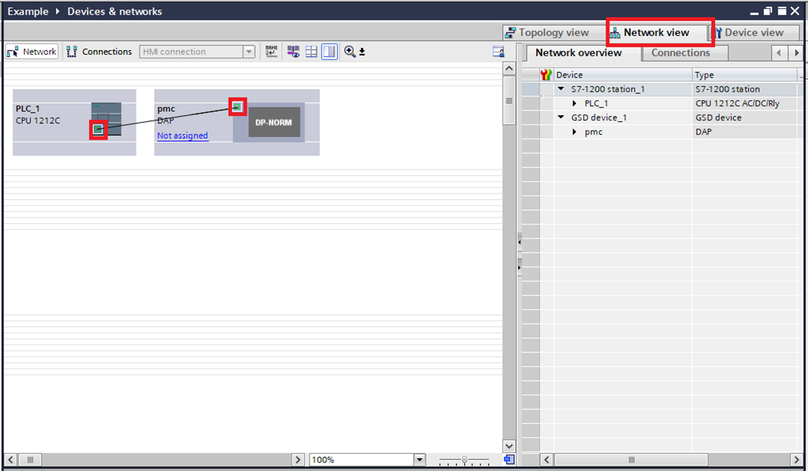
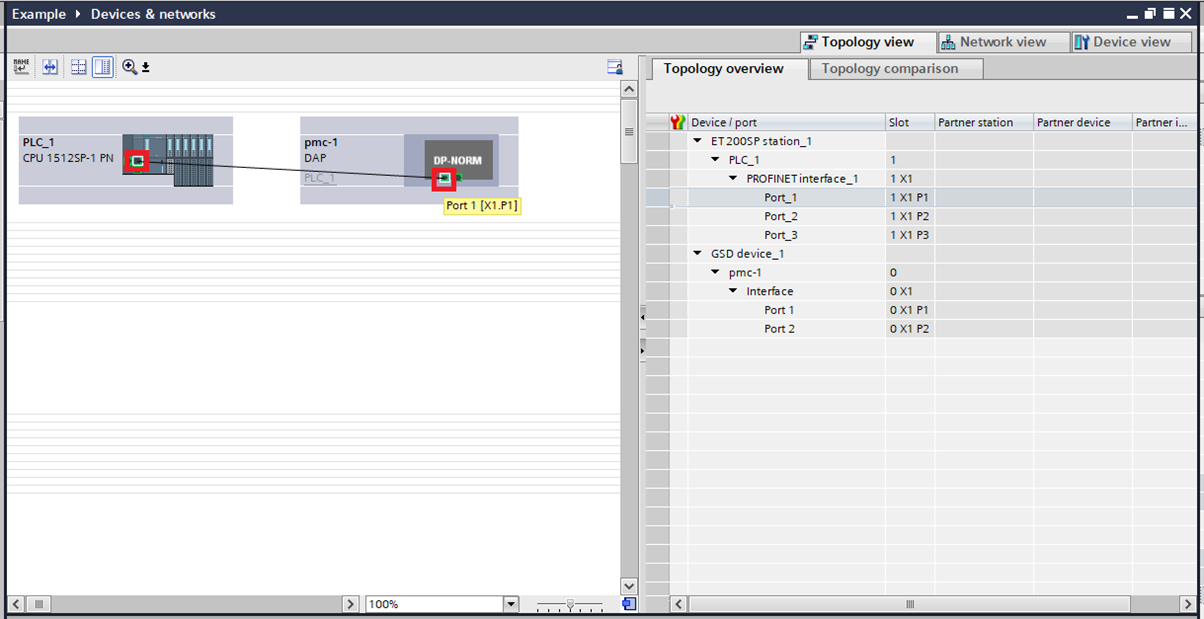
Step 7: In the Devices & networks window switch to the Network view. Connect the PLC to the PMC by clicking the port on the PLC and dragging it over to the port on the PMC
Step 8: In the Project tree expand the PMC and click Device configuration and enter the Device view tab. Then in the Hardware catalog go to Other field devices>PROFINET IO->I/O->Planar Motor Incorporated->Profinet->Module->Input and drag and drop the two devices into the Device overview of the PMC. Then do the same thing for the two devices in the Output folder
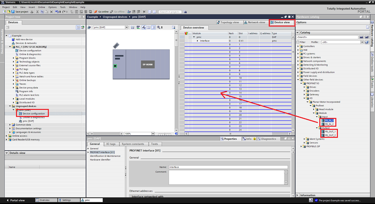
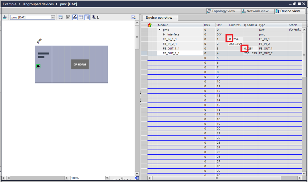
Step 9: Make a note of the starting addresses of the FB_IN and the FB_OUT. If you need to change this to prevent a device conflict you will need to change something else during the library setup
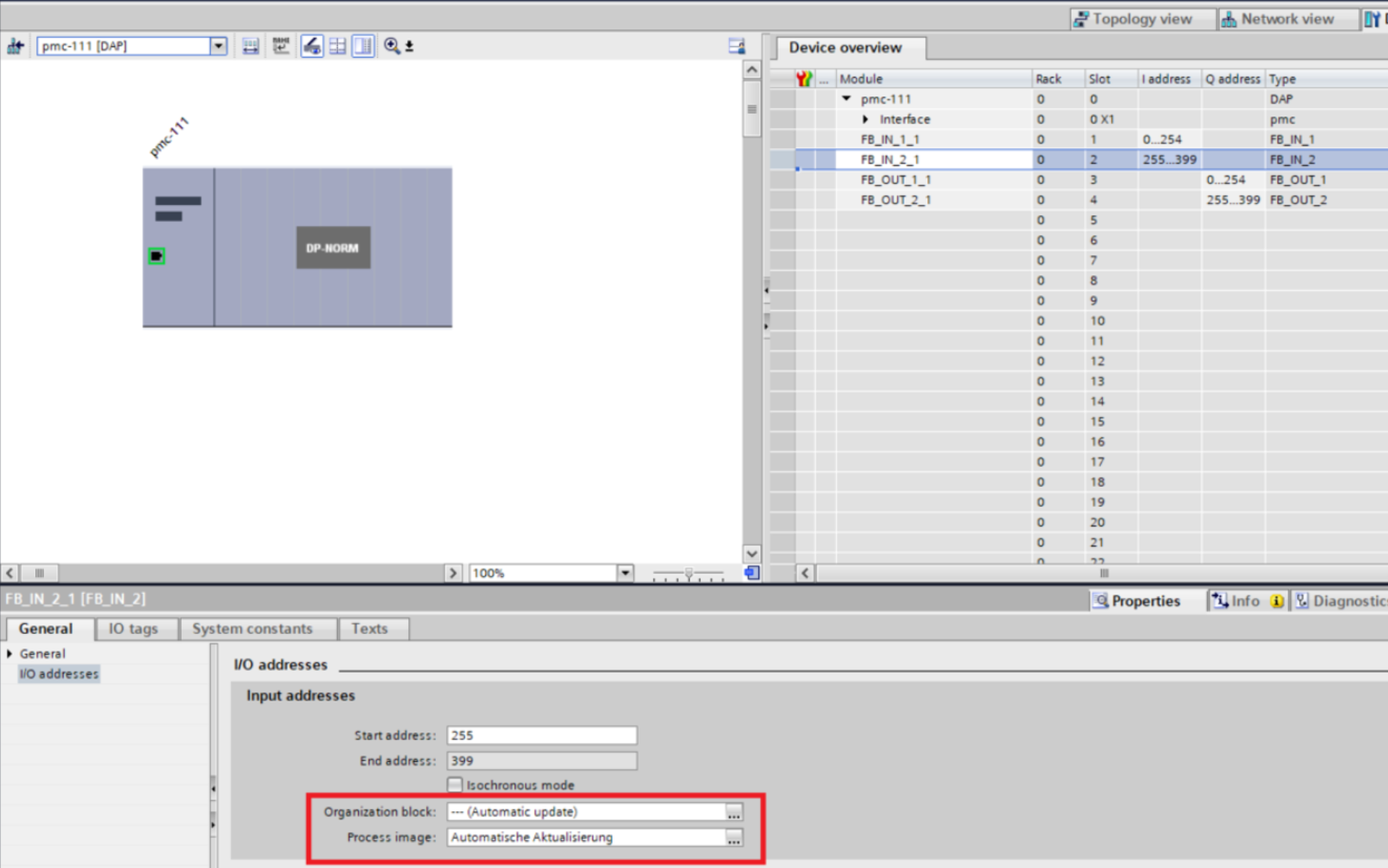
Step 10: Select each I/O variable (eg. FB_IN_1_1), and make sure the I/O addresses's "Organization Block" and "Process image" are set to "Automatically Update".
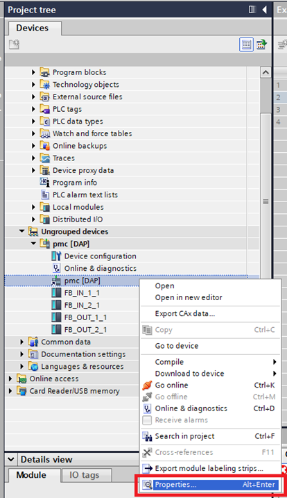
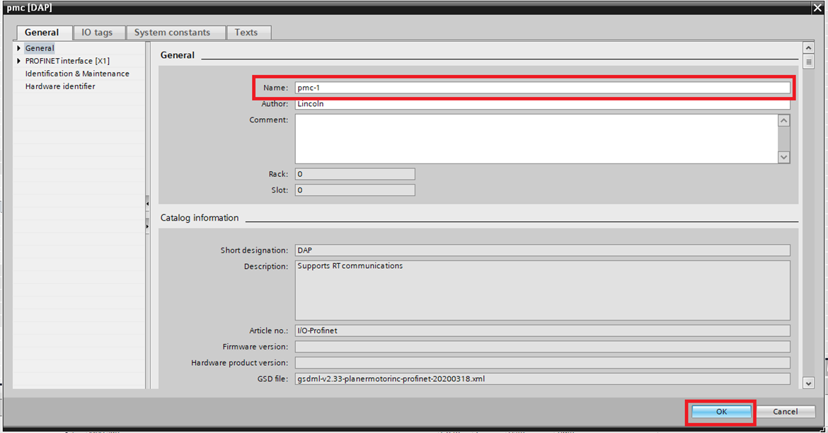
Step 11: Right click the PMC and click "Properties"
Step 12: In the pmc[DAP] window change the Name so that it matches the Device Name in the Planar Motor Tool. Then click "OK"
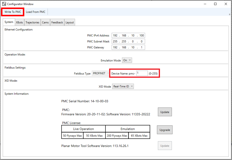
Step 13: The Device Name in the Planar Motor Tool can be found by clicking Configuration->Open Configurator and then accessing the System tab. Make sure that this matches the PMC name in Siemens TIA, then click on "Write To PMC"
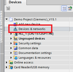
Step 14: Click on Device and Networks
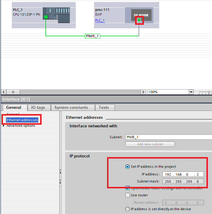
Step 15. Click on the Ethernet port of the PLC and record the IP address specified
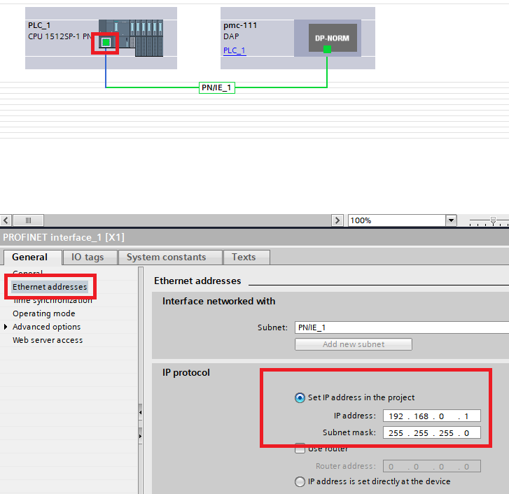
Step 16. Click on the Ethernet Port of the PMC, make sure the IP address of the PMC is on the same subnet as the PLC, but is different from the PLC and other devices on the profinet network.
Import and use library
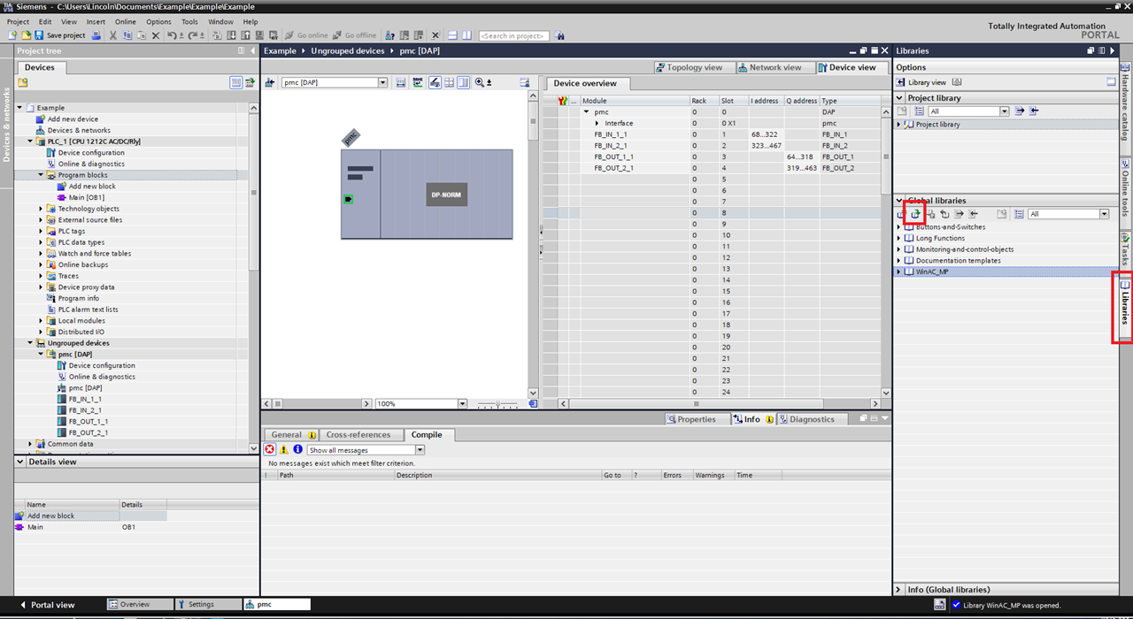
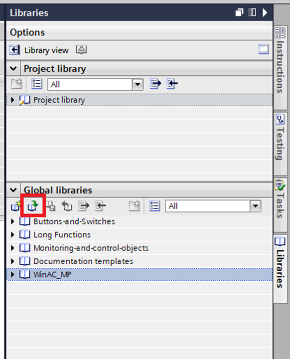
Step 1: Access the Libraries tab and then click the "Open global library" button
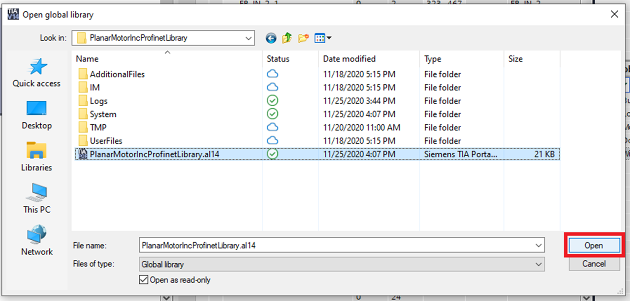
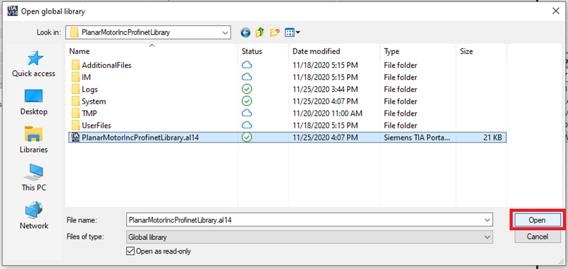
Step 2: In the Open global library window browse to the included .al14 file and click "Open"
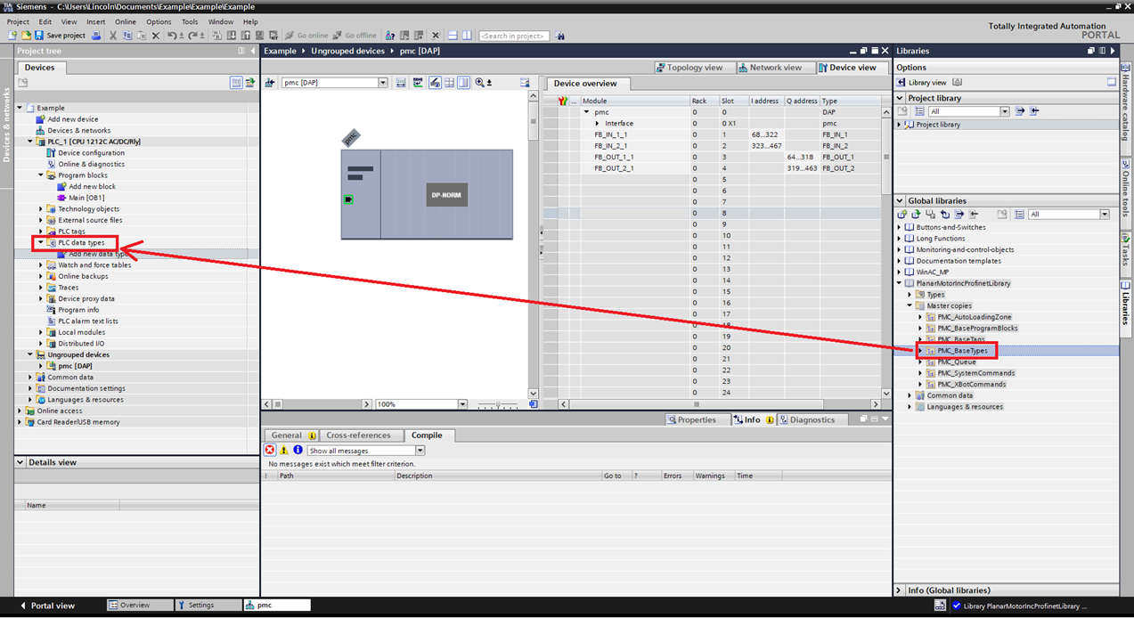
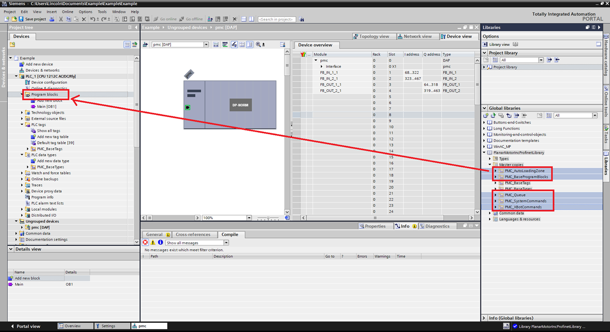
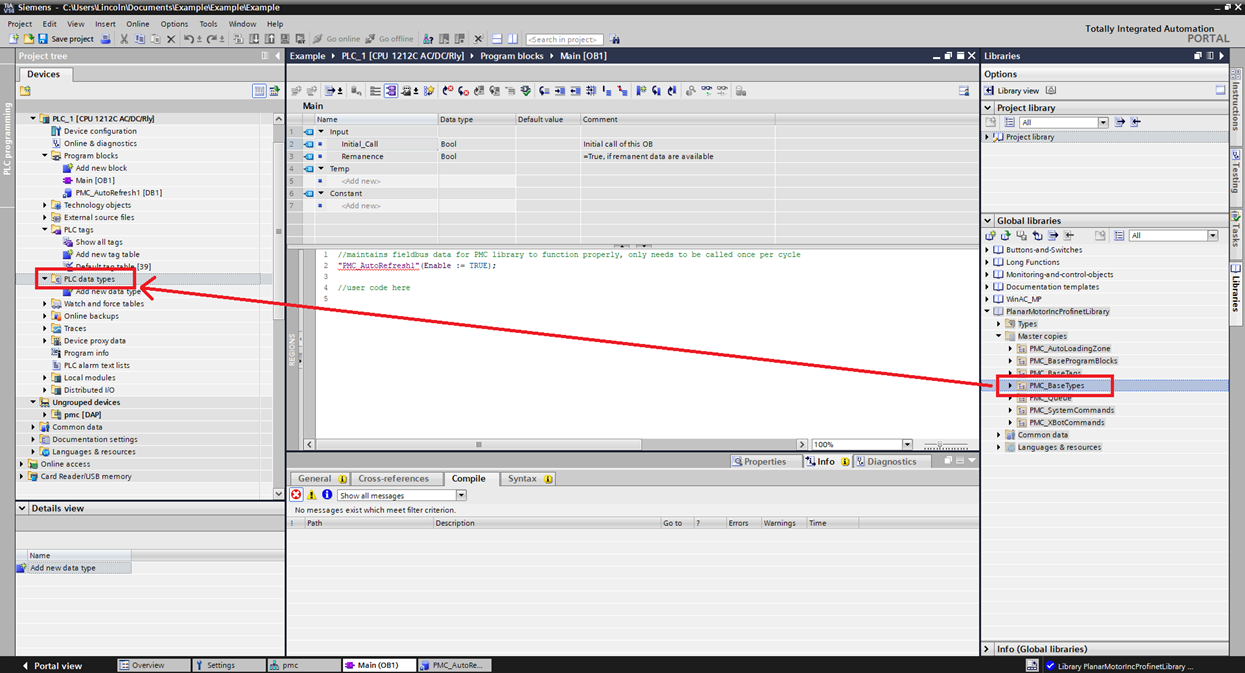
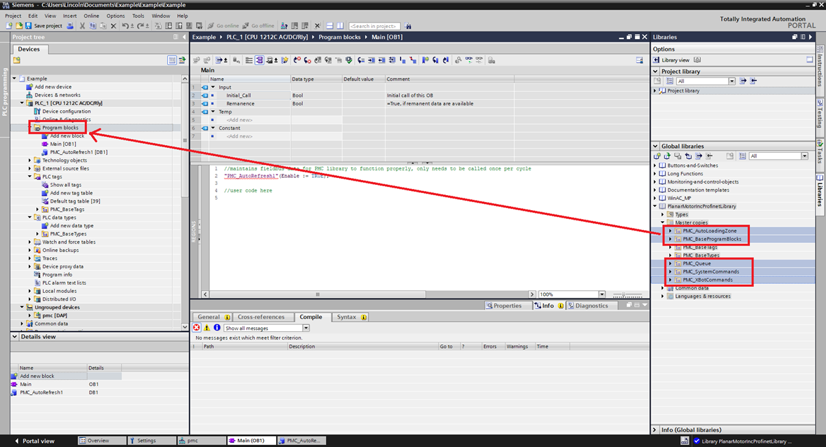
Step 3: Expand PlanarMotorIncProfinetLibrary->Master copies. Then drag and drop the PMC_BaseTypes folder from the Global Libraries over into PLC data types in the Project tree
Step 4: Drag and drop the rest of the folders into the Program blocks
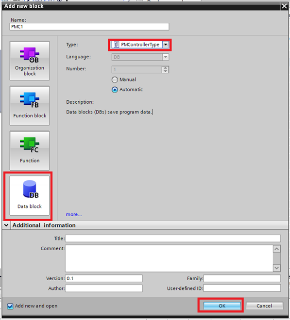
Step 5: Create a new Data block of Type PMControllerType and click OK
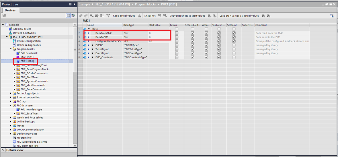
Step 6: Click the PMControllerType data block you just created. Make sure that DataToPMC matches the starting address of the FB_OUT. Make sure that DataFromPMC matches the starting address of the FB_IN. These will match by default, but if you need to change the address of FB_IN or FB_OUT you will need to change these.
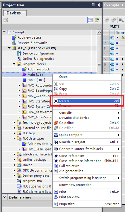
Step 7: These example uses structured text. The library works with ladder logic too, but this example sticks to structured text. Delete the default Main Organization block (default is ladder logic) by right clicking on it and clicking Delete
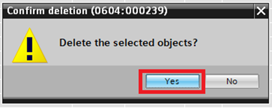
Step 8: Click Yes in the Confirm deletion window
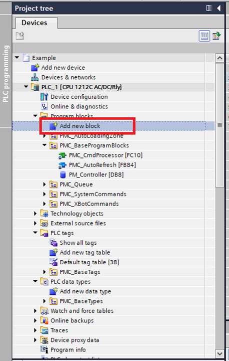
Step 9: Click "Add new block" in Program blocks folder
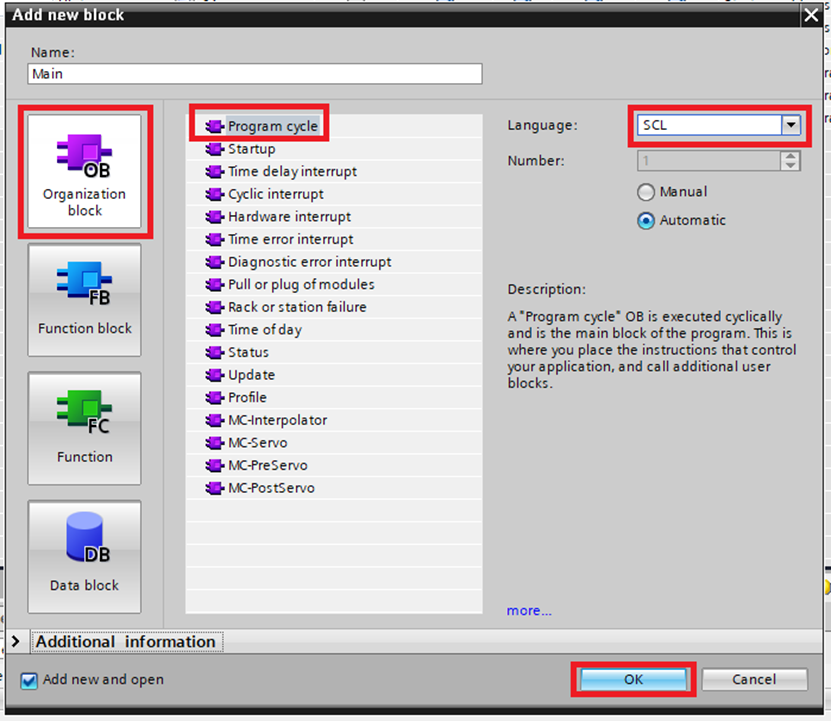
Step 10: In the Add new block window choose Organization block, select Program cycle, change the name to Main, and change Language to SCL. Then click "OK"
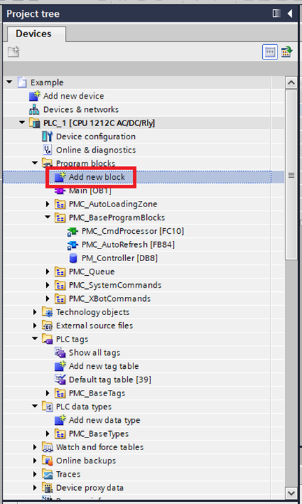
Step 11: Then click "Add new block" in the Program blocks folder again
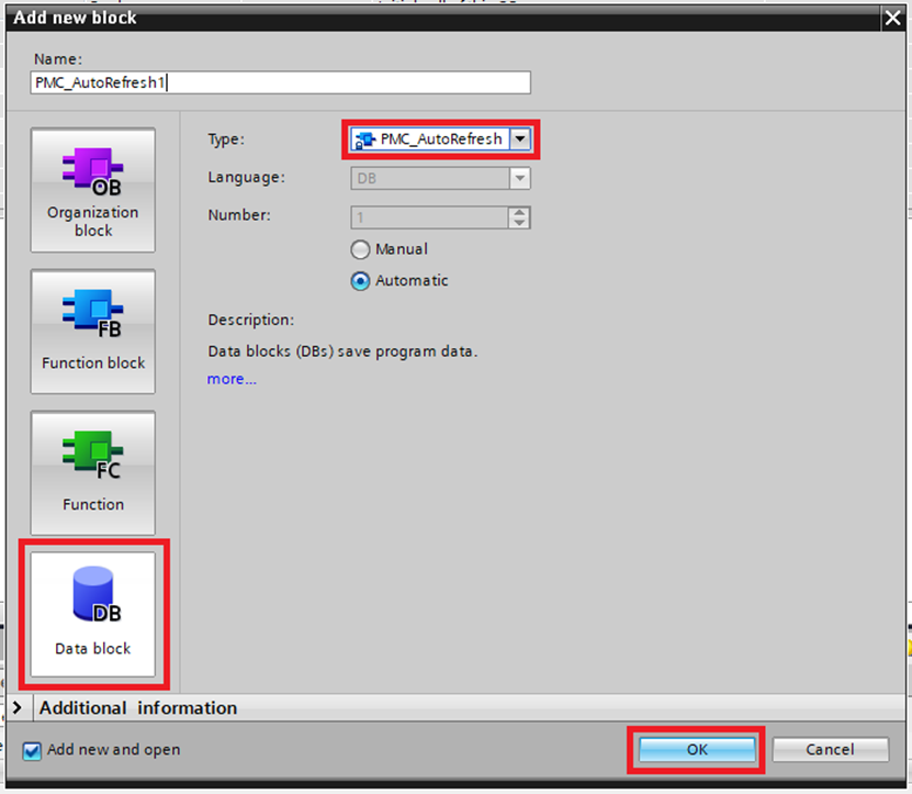
Step 12: In the Add new block window choose Data block. For the type choose PMC_AutoRefresh then click "OK". This should be the one and only instance of the PMC_AutoRefresh function block declared in this project
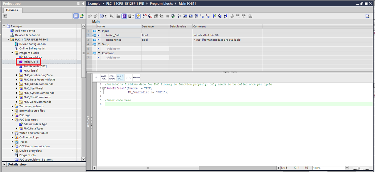
Step 13: In the Main make sure that the instance of the PMC_AutoRefresh function block is called once and only once per PLC cycle
Upgrade Library
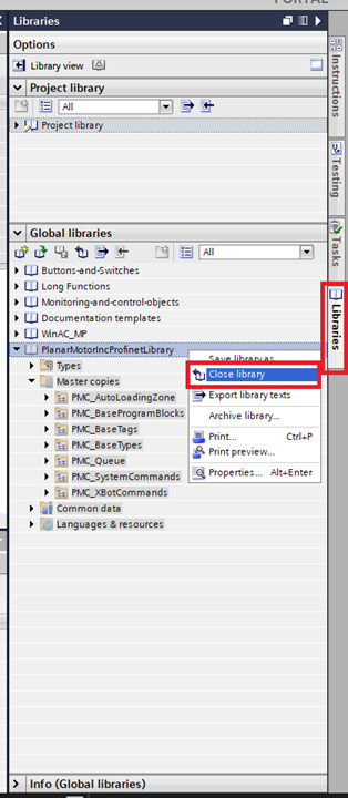
Step 1: In the Libraries tab click Close library on the old library
Step 2: Then click the "Open global library" button
Step 3: Browse to the new library then click "Open"
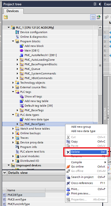
Step 4: Delete the old PMC_BaseTypes folder
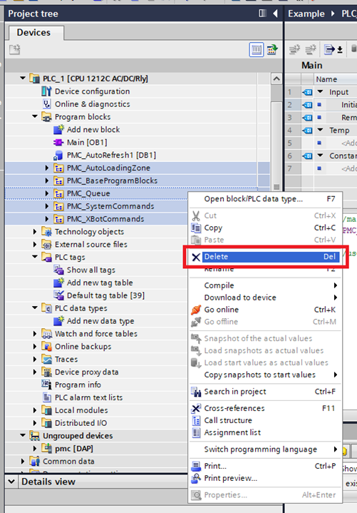
Step 5: Delete the rest of the old PMC program block folders
Step 6: Drag and drop the new PMC_BaseTags folder to the PLC data types folder
Step 7: Drag and drop the rest of the new PMC folders to the Program blocks folder
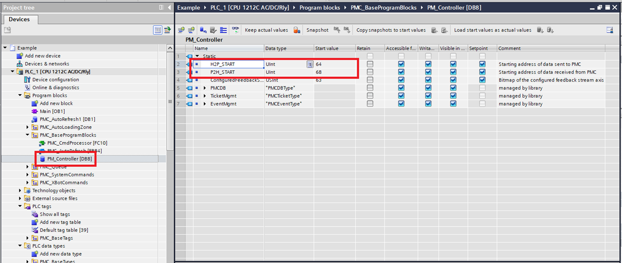
Step 8: Click Program blocks->PMC_BaseProgramBlocks->PM_Controller. Make sure that H2P_START (Host to PLC) matches the starting address of the FB_OUT. Make sure that P2H_START (PLC to Host) matches the starting address of the FB_IN. These will match by default, but if you need to change the address of FB_IN or FB_OUT you will need to change these
Setup Streaming (Optional) - for Profinet IRT
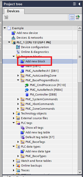
Step 1: In the project tree click "Add new block".
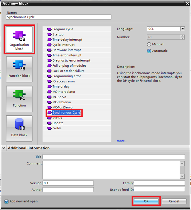
Step 2: In the Add new block window select "Organization Block", then select "Synchronous Cycle", then click "OK".
Step 3: Go into the "Device configuration" and select "Topology view".
Step 4: In the Topology view connect the port on the PMC, to the port on the PLC/switch that physical PMC is connected to. Make sure that this matches the actual physical connections.
Step 5: Switch to the "Network view" and select the PLC.
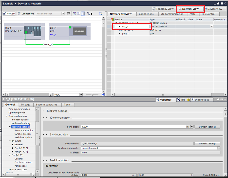
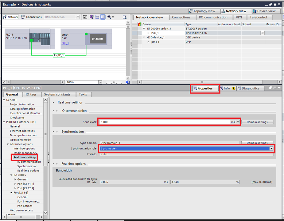
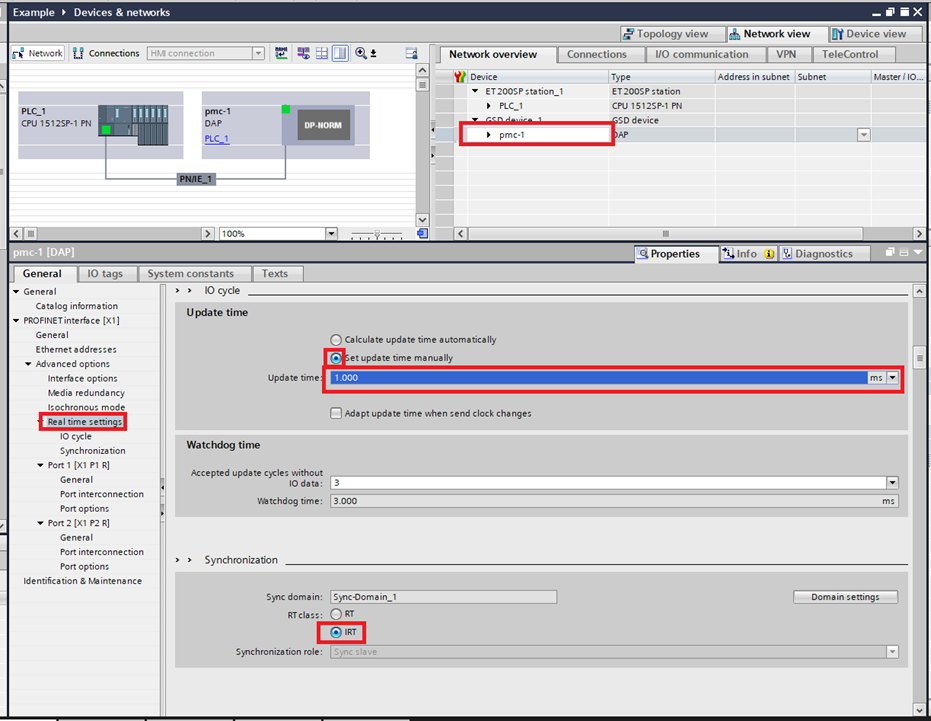
Step 6: Go into "Properties". Then select "Profinet Interface [X*]\ Advanced options\Real time settings". The Profinet interface should be the port that is connected to the PMC. Change the "Synchronization role" to "Sync master" then change the "Send clock" to the desired PLC cycle time.
Step 7: Still in the Network view select the PMC. Go into "Real time settings". Change the "RT" class to "IRT". Then check that the "Update time" matches the Send clock of the PLC. If it does not, check Set update time manually and use the drop down menu to change the Update time on the PMC to match the Send clock of the PLC
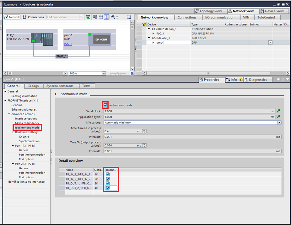
Step 8: Then select "Isochronous mode" in the PMC Properties. Enable "Isochronous mode", then enable Isochronous mode on all four of the modules in the "Detail overview".
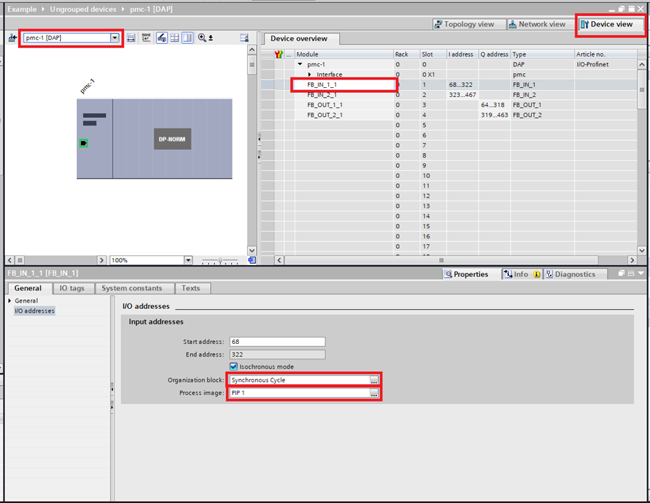
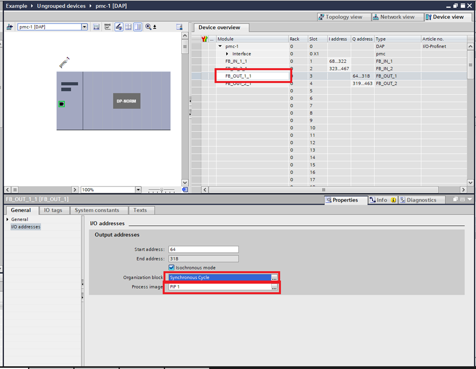
Step 9: Go into the "Device view" and select the PMC. Then select the first of the modules "FB_IN_1_1". In I/O addresses select the "Synchronous Cycle" block created earlier for the "Organization block". Take note of which Process image is being used. This will need to be the same for the entire PMC.
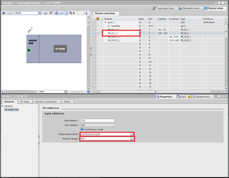
Step 10: Do the same for "FB_IN_2_1". Make sure that the Process image is the same.
Step 11: Do the same for "FB_OUT_1_1". Make sure that the Process image is the same.
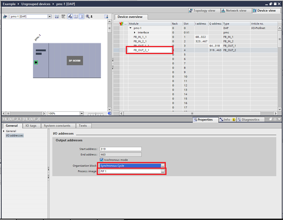
Step 12: Do the same for "FB_OUT_2_1". Make sure that the Process image is the same.
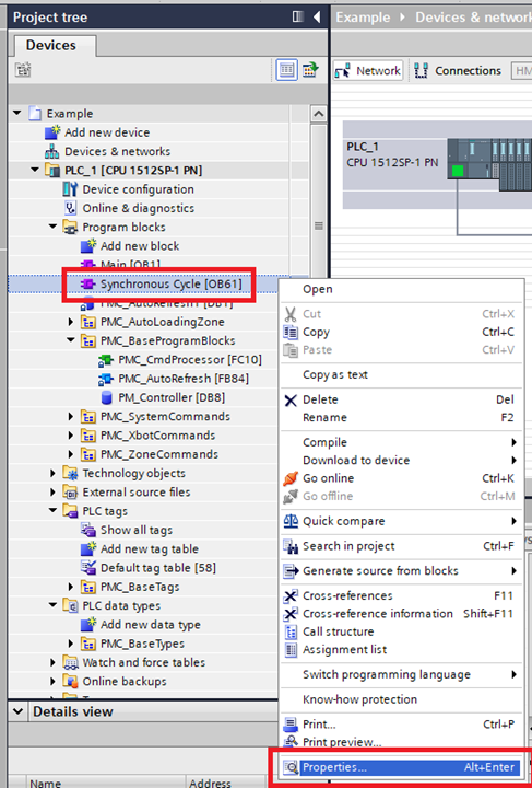
Step 13: In the Project tree right-click on the "Synchronous Cycle" block and click "Properties".
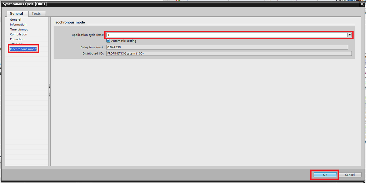
Step 14: In the window select "Isochronous mode". Check that the "Application cycle (ms)" matches the Send clock of the PLC. If it does not turn off Automatic setting and manually change it so that it matches.
Step 15:
-
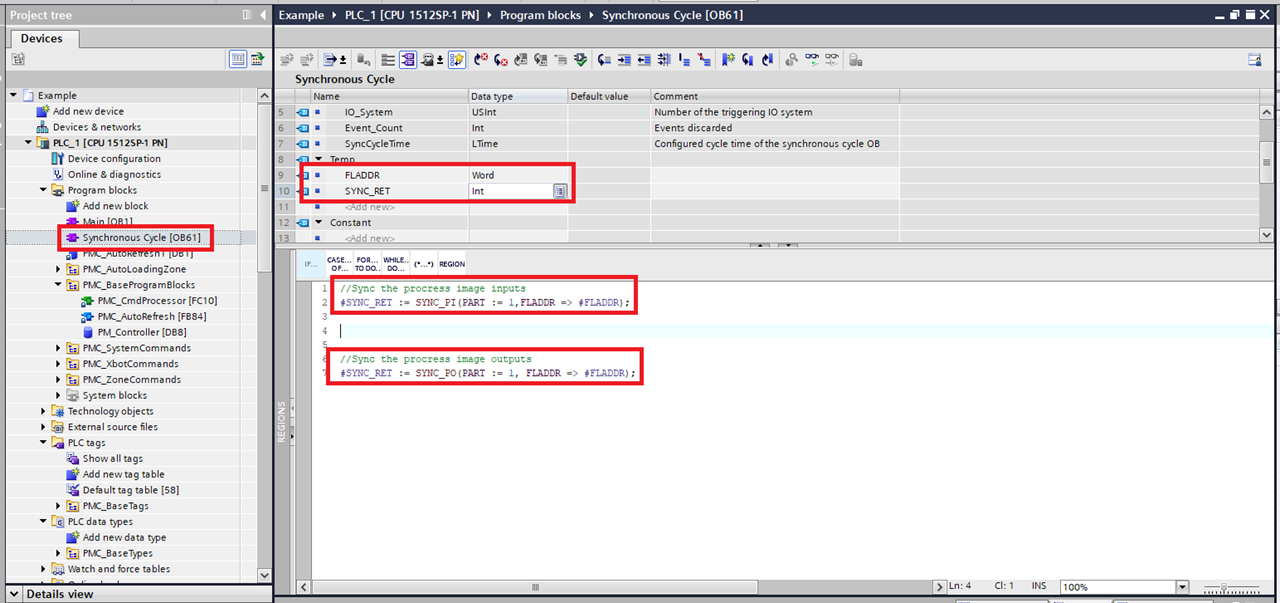
Open the Synchronous Cycle block. Add a Temp Word variable (named FLADDR in this example) and a Temp Int variable (named SYNC_RET in this example) to the block.
-
Add a SYNC_PI call to the beginning of the block. For the PART input use the number of the Process image selected earlier. For the FLADDR input use the Temp WORD variable. For the output use the Temp Int.
-
Add a SYNC_PO call to the end of the block. For the PART input use the number of the Process image selected earlier. For the FLADDR input use the Temp WORD variable. For the output use the Temp Int.
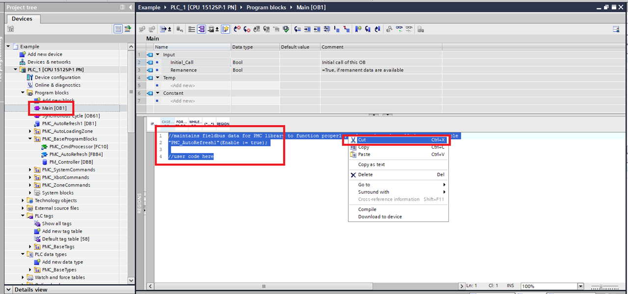
Step 16: Next go into the "Main" block and Cut out the code related to communicating with the PMC.
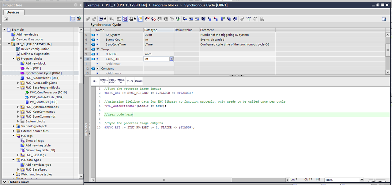
Step 17: Then paste the PMC related code into the "Synchronous Cycle" block.
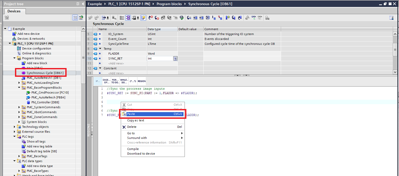
Step 18: Make sure that any PMC related code is between the SYNC_PI and SYNC_PO function calls.
File I/O on the PLC (Optional)
The following are one possible way to read and write files to the PLC storage. It could be helpful for commands such as Set PMC Configuration.
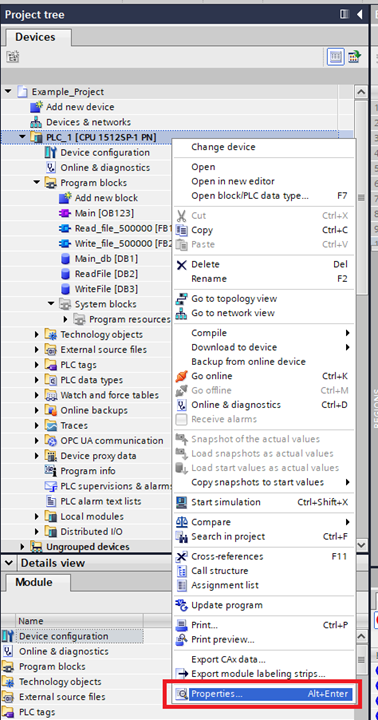
Step 1: To access the memory card online, the web server needs to be activated on the PLC. Go to the Project tree right click the PLC and click Properties…
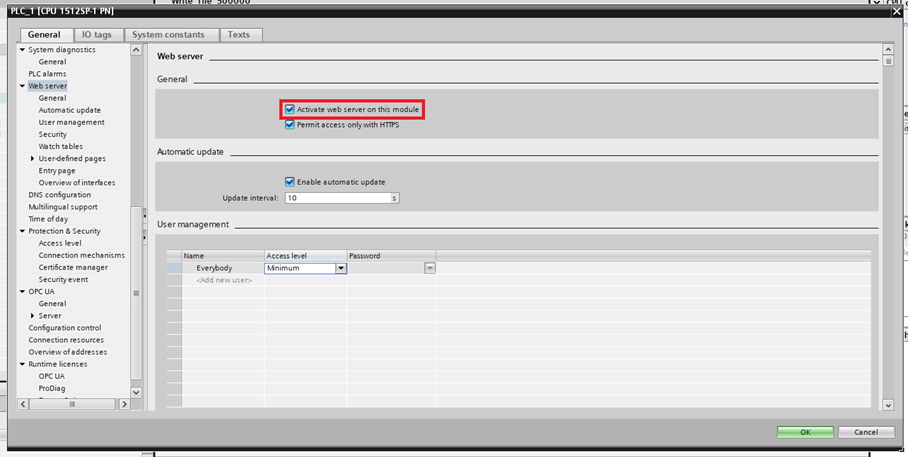
Step 2: In the General tab select Web server and click Activate web server on this module.
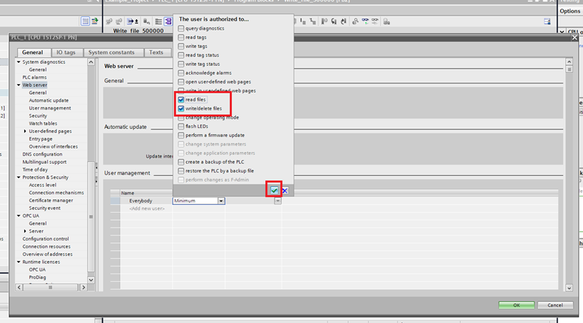
Step 3: Then in User management select the Access level of the user you will use (this example uses Everybody). Then enable “read files” and write/delete files” and click the green check mark button.
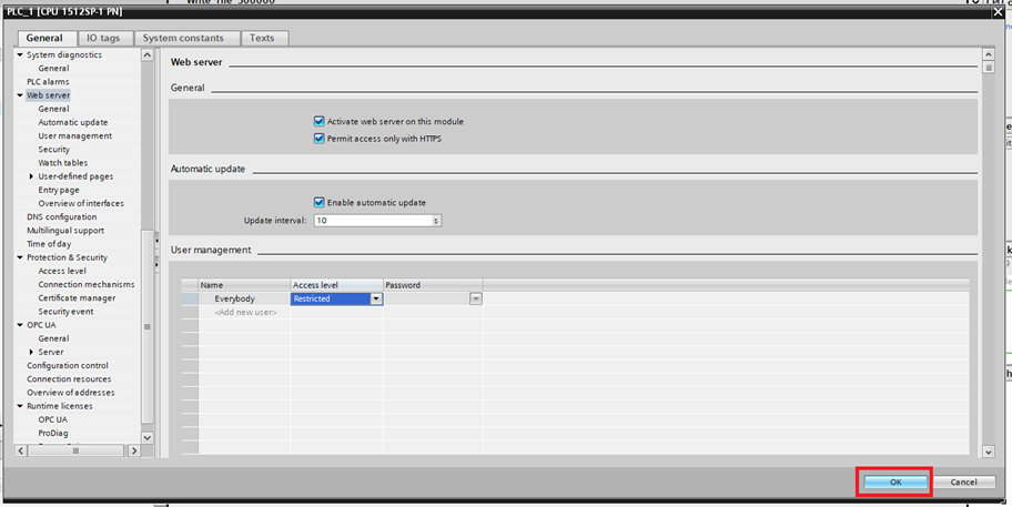
Step 4: Then click the OK button
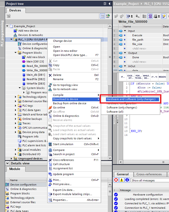
Step 5: Then download the changes to the PLC
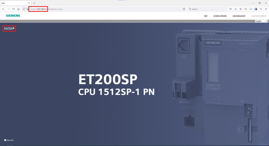
Step 6: To access the PLC web server, type the PLC’s IP address into a web browser. Once the intro page appears click ENTER.
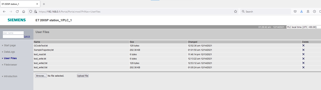
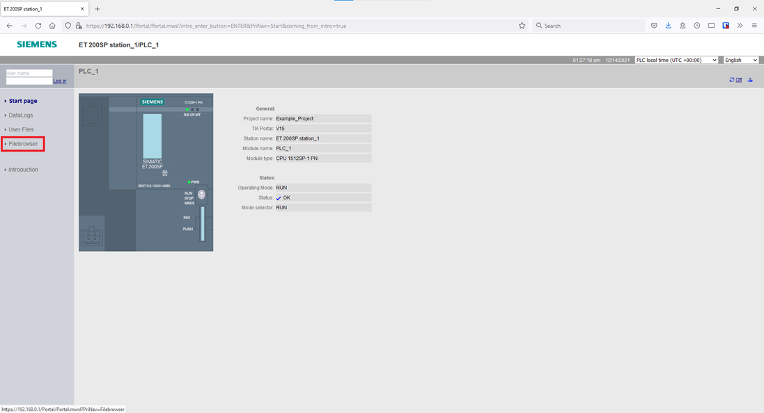
Step 7: You can access the files/folders on the memory card via the FileBrowser option on the right side.
Step 8: Here you can navigate, download, and upload files. However, the PLC can only access files in the “UserFiles” folder. You can only write to/delete from the “UserFiles” folder using the User Files option on the right side.
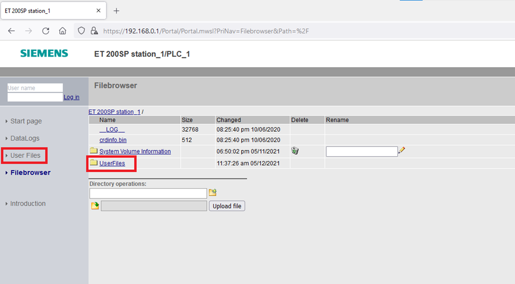
Step 9: Here you can upload, delete, and download the files that the PLC can actually access itself.