
The instructions differ depending on which power supply option is purchased. Please select accordingly.
PSB-1500-XX-YY-Z
This power supply comes pre-assembled with all necessary components securely mounted inside an ABS enclosure. The power supply will be set to the appropriate voltage for the series of flyways purchased.
It should be noted that the plastic housing of the Flyway Power Supply Prototype Box is not design for industrial use and the STO wiring inside the box is to bypass the STO to allow quick test.
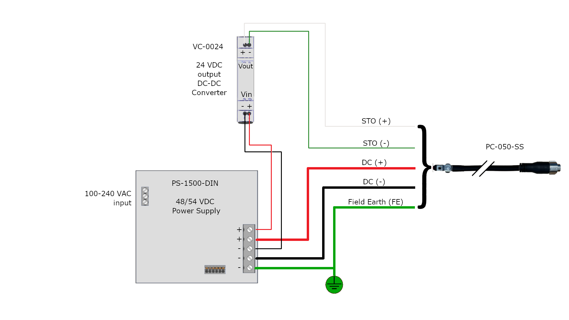
PS-1500-DIN
This power supply kit is provided for those customers who have their own enclosure, but still require the 48/54 VDC supply. This will be accompanied by a VC-0024 (24V DC-DC converter) to drive the STO signal. The power supply will be set to the appropriate voltage for the series of flyways purchased. The drawing below can be used to correctly wire the PS-1500-DIN, VC-0024 and any of the following power cables:
|
Length |
5m |
10m |
20m |
|---|---|---|---|
|
Cable |
PC-050-SR |
PC-100-SR |
PC-200-SR |
|
PC-050-SS |
PC-100-SS |
PC-200-SS |
The customer must supply their own 100-240 VAC input cord or method of powering the 48/54 VDC supply.
No Power Supply (externally supplied)
The diagram below is a general layout for connecting a customer supplied 48/54 VDC power supply with a customer supplied 30 A breaker and any of the following power cables:
|
Length |
5m |
10m |
20m |
|---|---|---|---|
|
Cable |
PC-050-SR |
PC-100-SR |
PC-200-SR |
|
PC-050-SS |
PC-100-SS |
PC-200-SS |
The STO signal diagram can be found here.
.png?cb=e08edda668f80a9f956599fdcbb169b1)