Emergency Stops (E-Stops) are a critical component in any automated or mechanical system, serving to protect human safety, prevent hazards, and minimize potential damage to equipment.
In the Planar Motor System, two key safety functions are particularly relevant:
-
Quick Stop – Enables a controlled deceleration and landing of XBots before power is removed.
-
Safe Torque Off (STO) – Immediately cuts all torque-generating power, preventing unintentional motion or restart.
1. Quick Stop
In emergency situations, XBots may still be moving at high speeds when the system is shut down. If power to the flyways is abruptly cut, the XBots will fall and if skid to a stop if they are in motion, which can lead to damaging the products they are carrying.
The Quick Stop function can be used to ensure a controlled landing when power to the system is cut. This feature can be triggered either with a hardware signal to the PMC or via a Fieldbus command. The Quick Stop is triggered on the falling edge of the Digital Input (black) wire of the PMC Power Cable, as shown below.

The Quick Stop feature initiates a controlled shutdown by sending a Stop and Deactivate command to the XBots, allowing them to decelerate safely before the flyway power is cut off.
Refer to Configure Digital Input To Quick Stop and Send Digital Input to PMC function blocks for instructions to trigger a Quick Stop from the PLC.
2. Safe Torque Off (STO)
Safe Torque Off (STO) is a safety mechanism that immediately disables all torque-generating power to a motor, preventing unintended movement or startups during emergencies or maintenance. When the STO signal is triggered, all power to the XBots is instantly cut off, and they cannot restart until the STO signal is cleared.
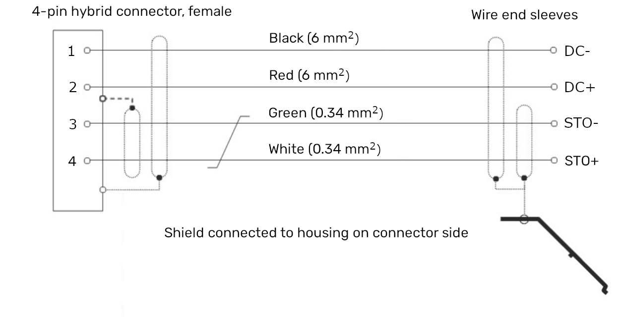
The STO function is triggered by a falling edge on the STO+ (white) pin.
For more details, refer to the Power Cable PC-050-SR / PC-100-SR / PC-200-SR.
Combined Safety Implementation: Quick Stop + STO Delay
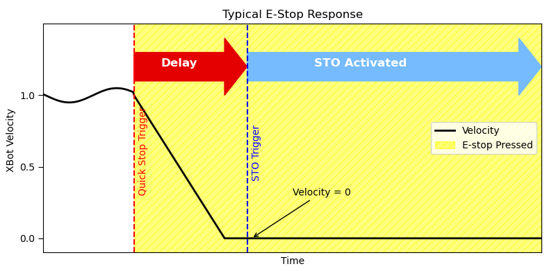
One possible implementation that utilizes both safety mechanisms is to trigger a Quick Stop with an immediate falling edge, followed by a delayed STO cut-off to allow the XBots to decelerate and land safely.
When the emergency signal is activated:
-
The falling edge on the PMC Digital Input triggers the Quick Stop, initiating deceleration and landing of the movers.
-
After a short delay (recommended between 200 – 500 ms), the STO signal is triggered by pulling STO+ (white) low, cutting power to the flyways.
By the time STO+ signal is low, triggering the STO, the movers will have already landed. Once STO is engaged, the power stage cannot be re-enabled until the E-Stop switch is manually reset.
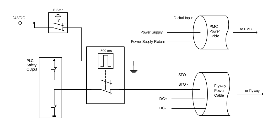
An example implementation is shown below:
-
The E-Stop button generates an immediate falling edge to the PMC Digital Input, triggering the Quick Stop.
-
After a 500 ms delay, the STO+ line is pulled low to engage STO.
-
The PLC Safety Output is also connected to the STO+ and STO− lines as a redundant safety measure.
Users are encouraged to implement the emergency triggering logic using any method that meets safety requirements.
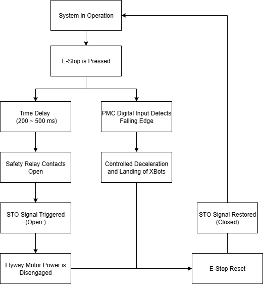
A example flowchart is shown below to aid understanding.