Library Setup
Creating a new project
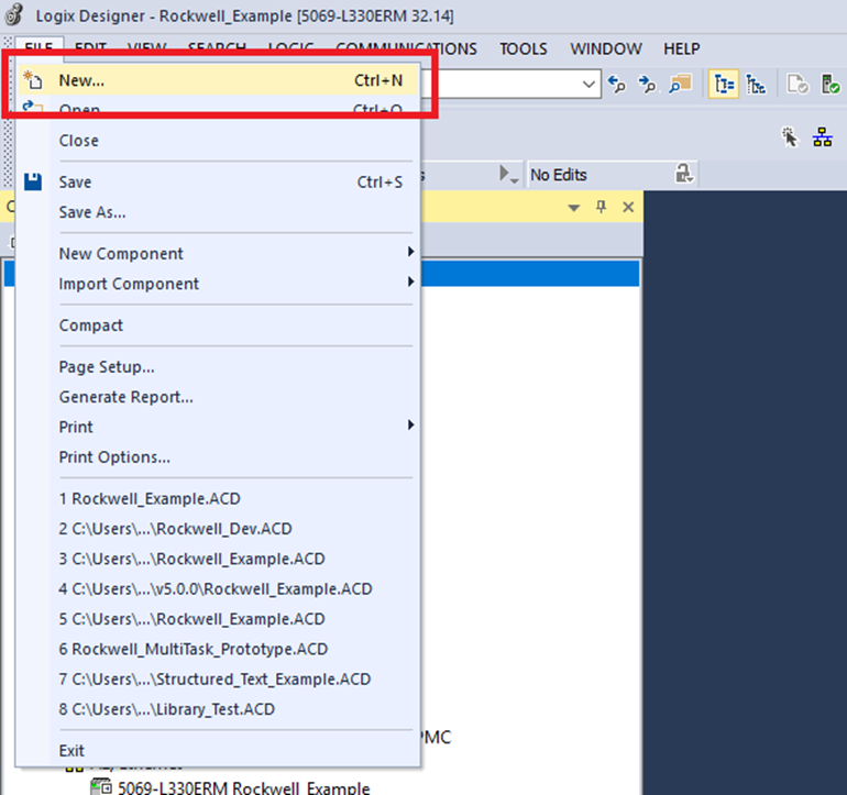
Step 1: Click on File->New
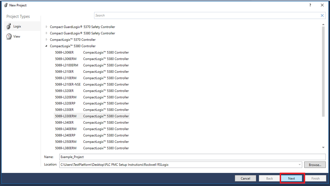
Step 2: In the New Project window select the controller that will be used, give the project a name and location. Then click "Next"
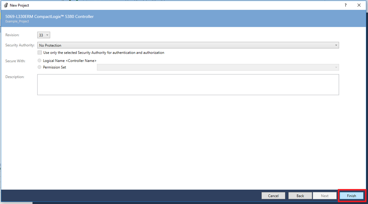
Step 3: Choose Revision number (>= 32) and Security Authority as shown below. Then click "Finish"
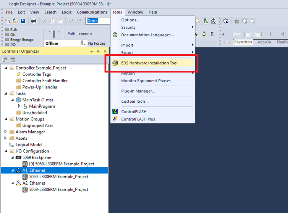
Setup Fieldbus
Step 1: Click Tools->EDS Hardware Installation Tool
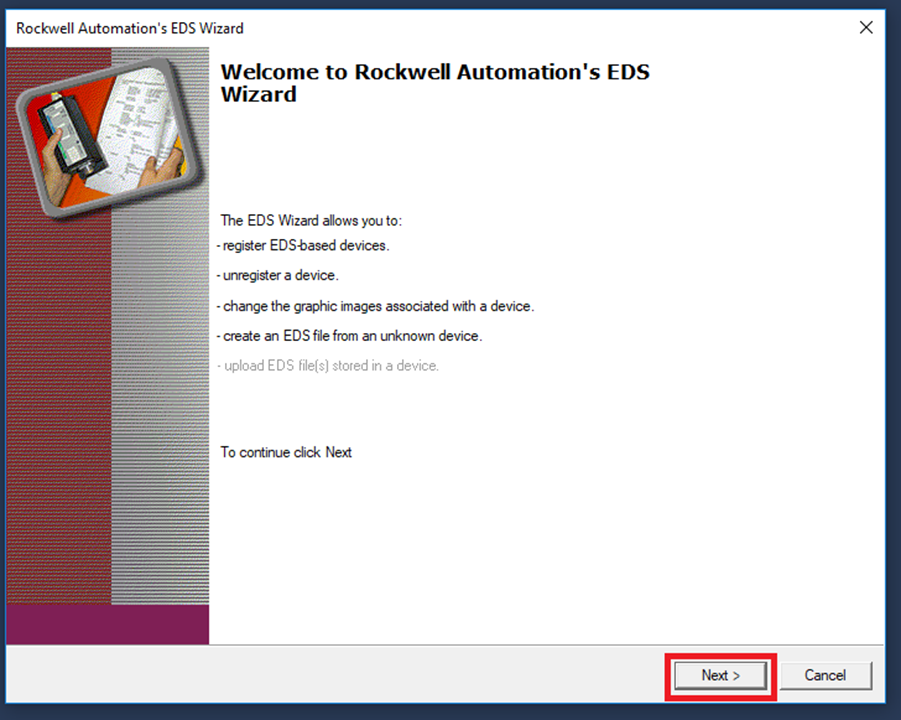
Step 2: In the Rockwell Automation’s EDS Wizard window click "Next"
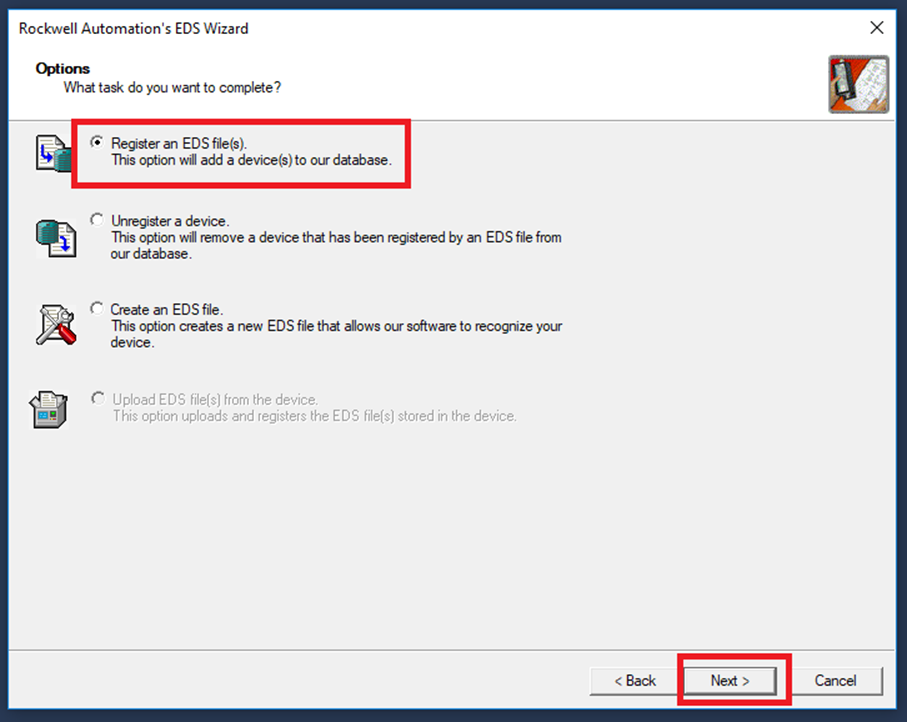
Step 3: Select Register an EDS file(s) then click "Next"
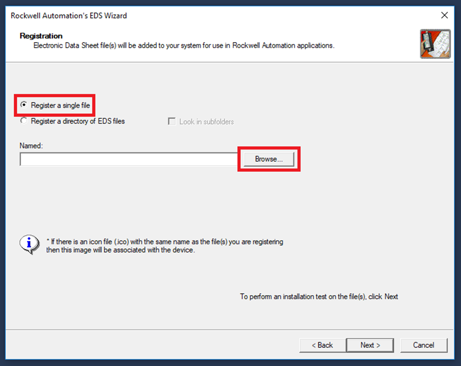
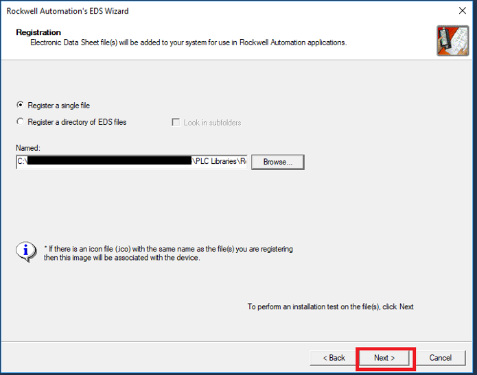
Step 4: Select Register a single file then click "Browse..."
Step 5: Browse to the include .eds (Electronic Data Sheet) file and click "Open"
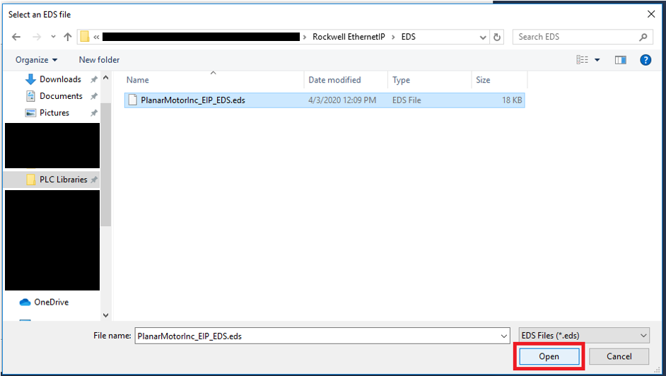
Step 6: Click "Next" once the EDS file has been selected
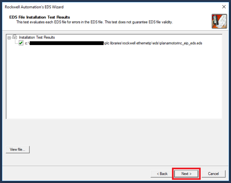
Step 7: Click "Next" once the EDS passes the test
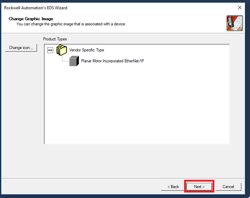
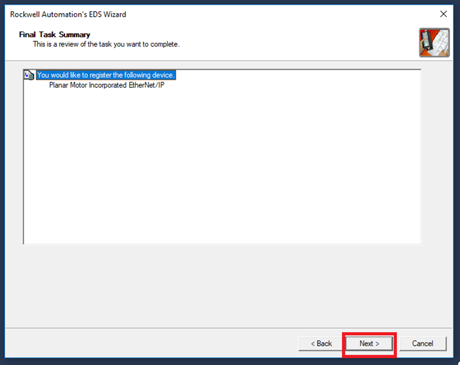
Step 8: Click "Next"
Step 9: Click "Next"
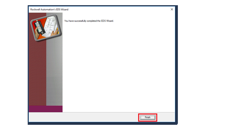
Step 10: Click "Finish"
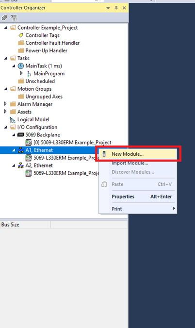
Step 11: In the Controller Organizer expand the I/O Configuration and right click on the Ethernet port that the PMC is connected to on the PLC. Then click "New Module"
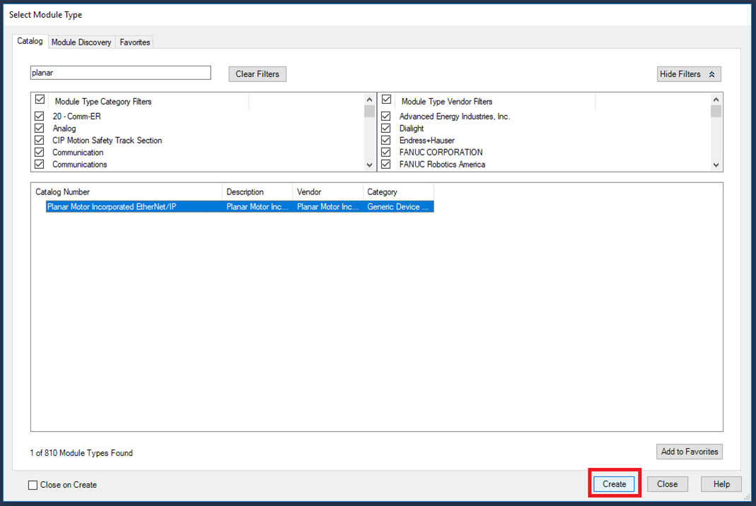
Step 12: In the Select Module Type window in the Catalog tab search for Planar Motor and select Planar Motor Incorporated EtherNet/IP and click "Create"
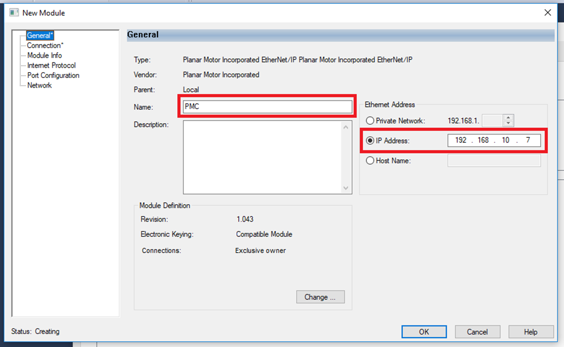
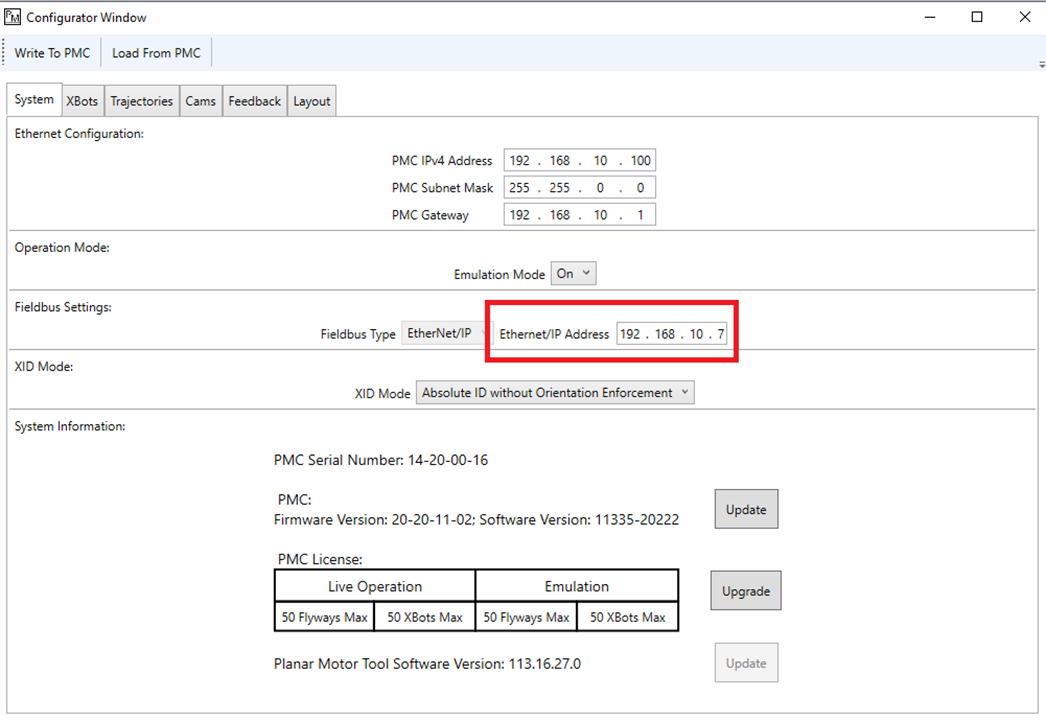
Step 13: In the New Module window make the follow changes. In the General section give the module a name. Then change the IP Address to match the one displayed in the Planar Motor Tool->Configuration->Open Configurator in the System tab under Ethernet/IP
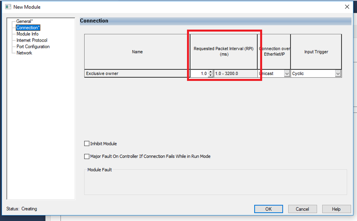
Step 14: In the Connection section make sure the Requested Packet Interval (RPI) is equal or shorter than the cycle time of the PLC task
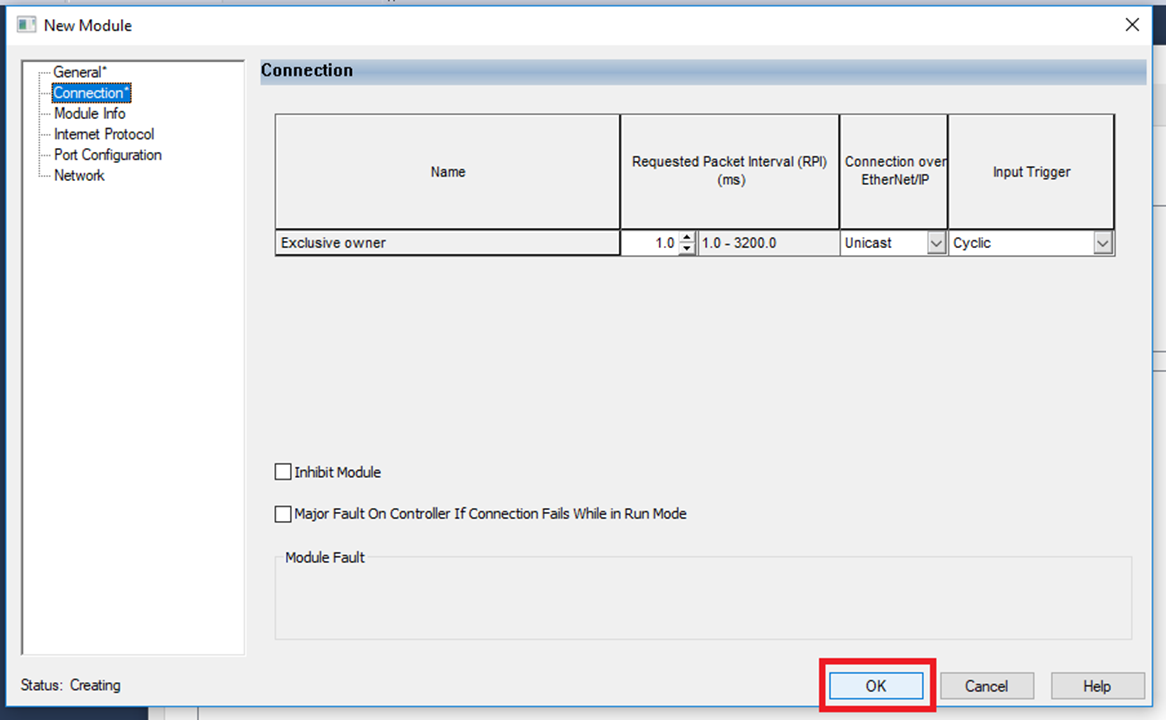
Step 15: Then click "OK"
Import and use library
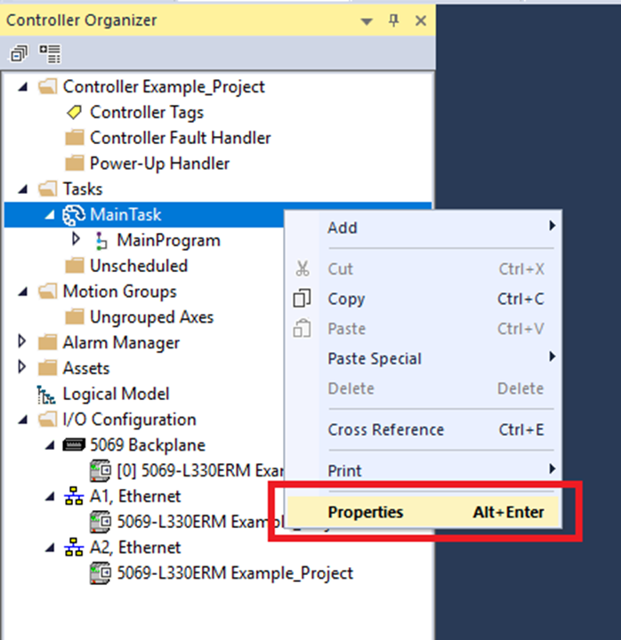
Step 1: The PMC library is designed for a periodic task. Rockwell Logix Designer projects default to continuous so we need to change that. First expand Tasks in the Controller Organizer and right click MainTask then click "Properties"
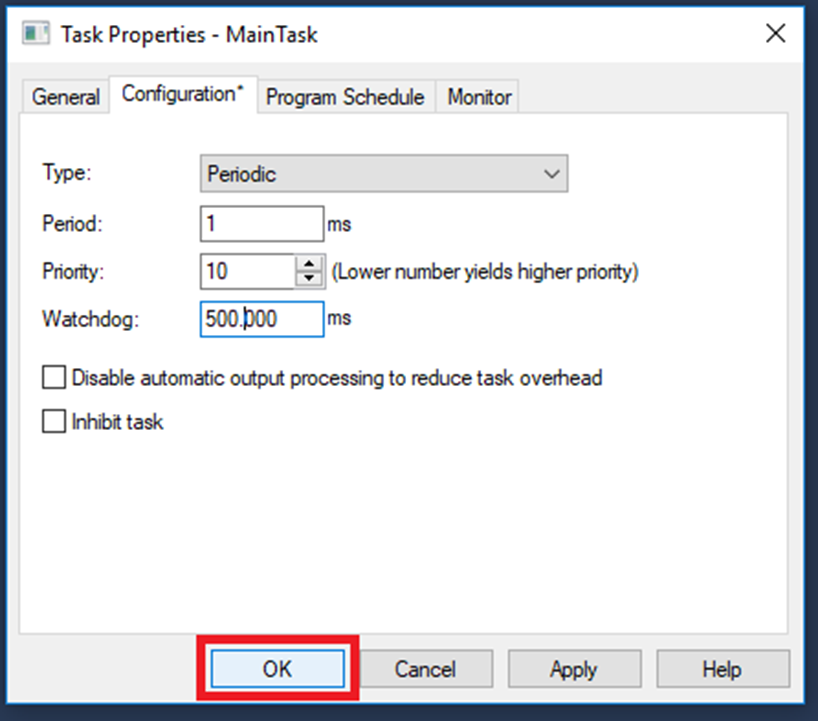
Step 2: In the Configuration tab of the Task Properties window change Type: to Periodic and choose a Period that is equal to or greater than the Request Packet Interval (RPI). Then click "OK"
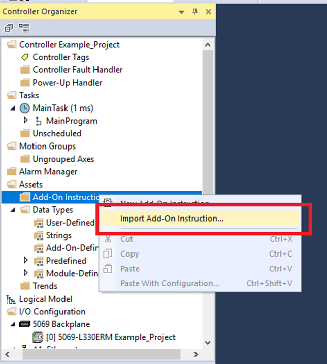
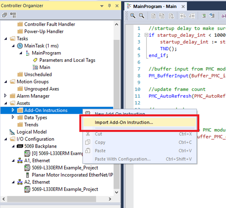
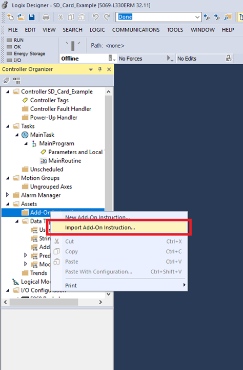
Step 3: Expand Assets in the Controller Organizer then right click Add-On Instructions then click "Import Add-On Instruction"
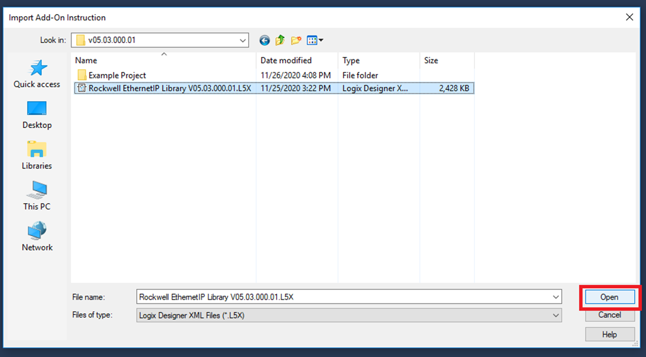
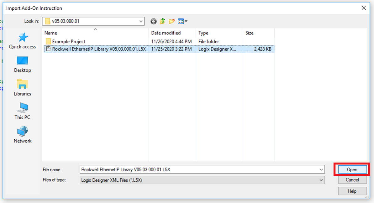
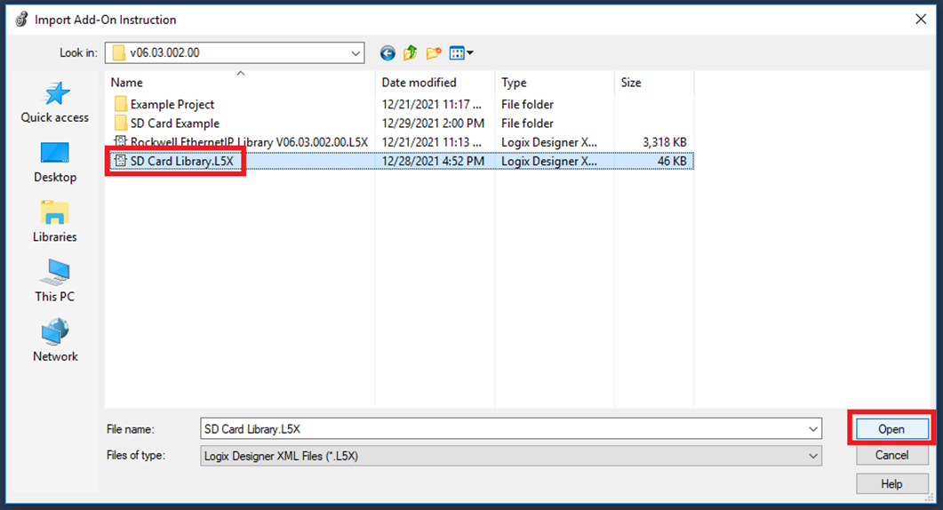
Step 4: In the Import Add-On Instruction window browse to the library .L5X file. Select it then click "Open"
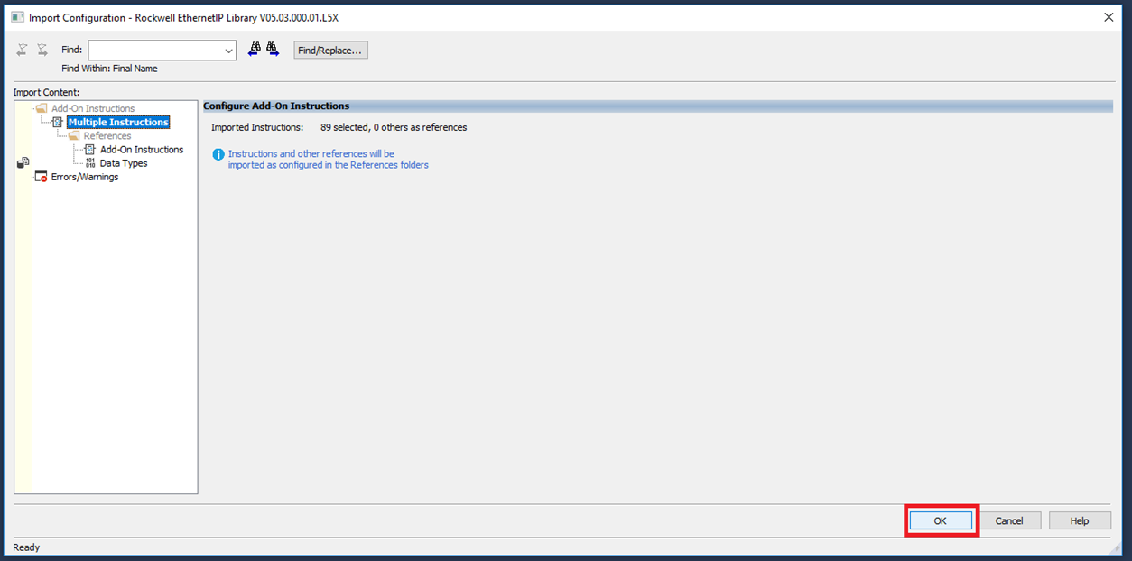
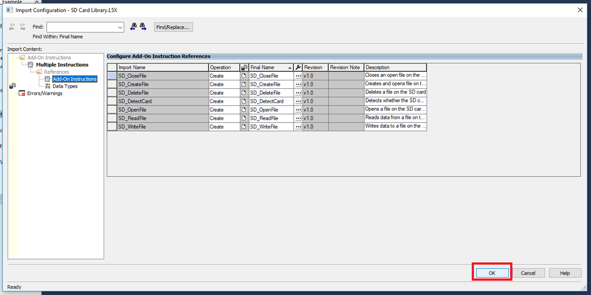
Step 5: Once the library is done being read (may take several minutes) the Import Configuration will appear. Click "OK"
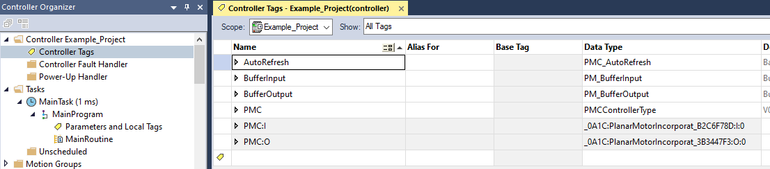
Step 6: Before using the library a number of steps must be done. Expand Controller in the Controller Organizer and click Controller Tags. Then go into the Edit Tags tab and declare the following variables as Controller Tags. These PMC datatypes: PM_BufferInput, PM_BufferOutput, PMC_AutoRefresh, and PMCControllerType should only be declared as Controller Tags and only once each.
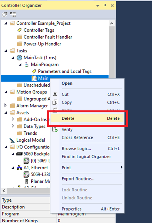
Step 7: For consistency with the included example project we will switch the Main routine from the default of Ladder Diagram to Structured Text. Expand Tasks->MainProgram right click Main and click Delete. (Note: the library is fully compatible with ladder diagram this is just so that it matches the example project)
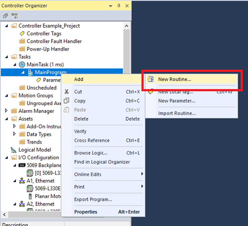
Step 8: Right click MainProgram and click Add->New Routine
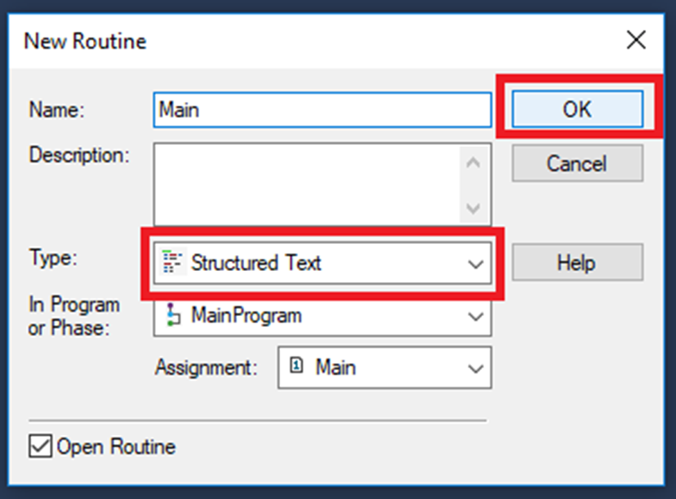
Step 9: In the New Routine window change the Type: to Structured Text and click "OK"
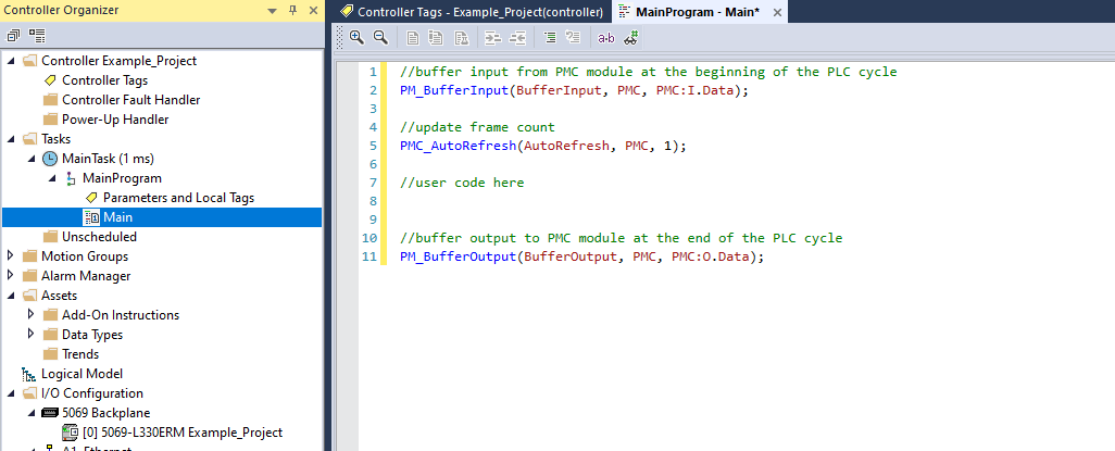
Step 10: In the Main routine make sure the follow is done:
-
Call the PM_BufferInput AOI once at the beginning of the PLC cycle
-
Call the PMC_AutoRefresh AOI once and only once per PLC cycle. Make sure that the AutoRefresh call is after the BufferInput call and before the BufferOutput call
-
Call the PM_BufferOutput AOI once at the end of the PLC cycle
For user code, all PMC AOIs other than PM_BufferInput, PM_BufferOutput require a PMCControllerType input. Use the one declared earlier as Controller Tag.
Upgrade Library
Step 1: Expand Assets and right click Add-On Instructions. Then click "Import Add-On Instruction"
Step 2: In the Import Add-On Instruction window browse to the new .L5X library file. Select it and click "Open"
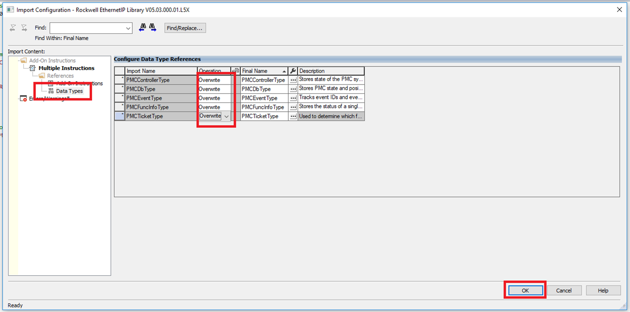
Step 3: In the Import Configuration window go to Data Types and make sure all the Data Types have the Operation set as Overwrite. Then click "OK"
File I/O on the PLC (Optional)
The following are one possible way to read and write files to the PLC storage. It could be helpful for commands such as Set PMC Configuration.
Step 1: Import SD Card library Add-On Instructions
Step 2: Confirm the Import by clicking OK. If you are upgrading from a previous version of the SD card library, make sure that all the Add-On Instructions and Data Types are set to Overwrite.
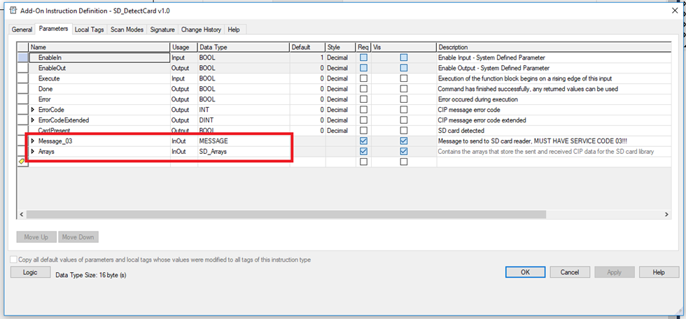
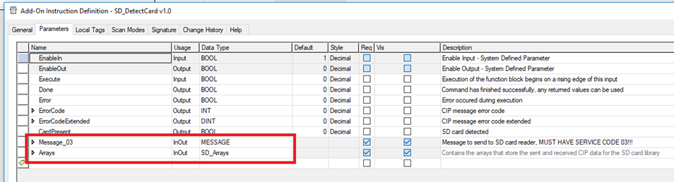
Step 3: The SD card Add-On Instructions (AOI) communicates with the SD card reader on the controller using CIP messages. To do this the AOI requires two InOut parameters. The first is a MESSAGE data type that contains parameters about the communication, and the second is a SD_Arrays data type that contains the arrays that store the data sent and received.
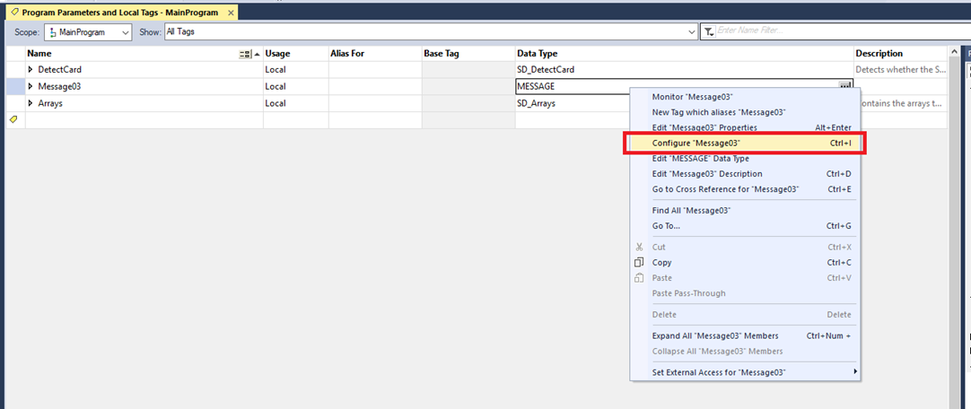
Step 4: The MESSAGE parameter used by the SD card AOI has some essential elements that can only be edited manually while offline. To do this go to the tag window and create an instance of the MESSAGE data type and an instance of the SD_Arrays data type. Then right click it and select Configure “Variable_Name”.
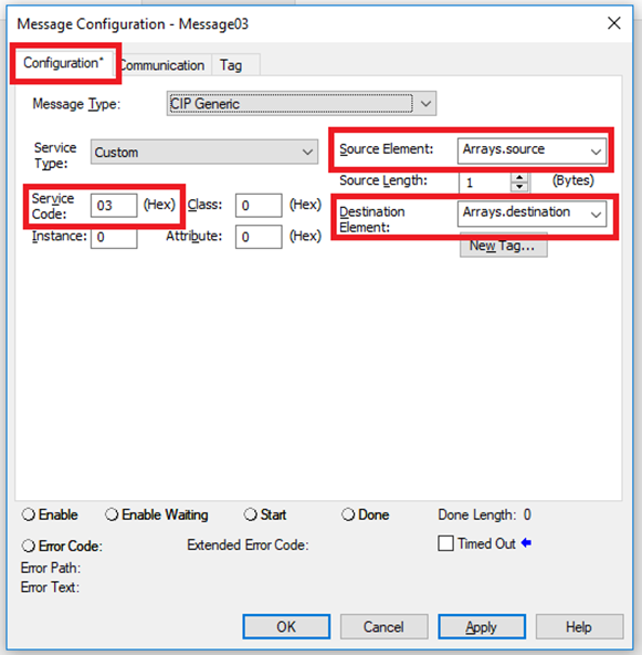
Step 5: In the Message Configuration window select the Configuration tab. For the Source Element type in the “source” member of the SD_Arrays Data Type instance. For the Destination Element type in the “destination” member of the SD_Arrays Data Type instance.
The Service Code will be different depending on which SD card AOI the message will be used with. For example, the SD_DetectCard AOI requires a service code of 03.
Step 6: Technically only the Source Element, Destination Element, and Service Code need to be edited manually. However, the Message Configuration window won’t let you apply the changes unless you also have a valid Path. So go to the Communication tab and click Browse.
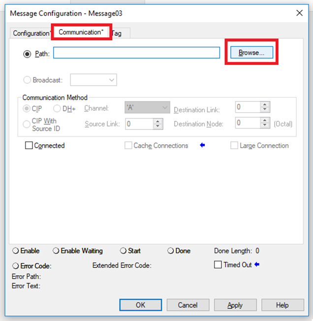
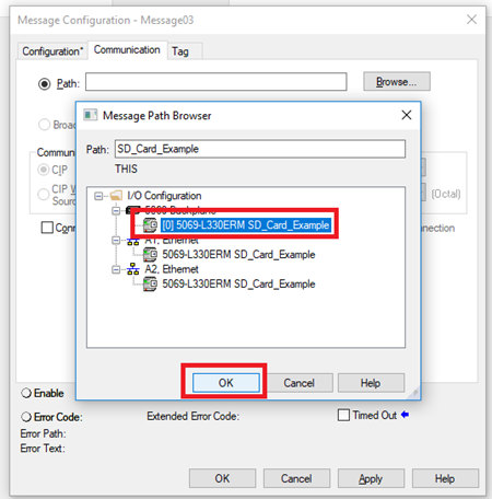
Step 7: Then select any option here. The SD card AOI will change the path to the right option for the SD card, this is just so that the Message Configuration window will let us apply the changes.
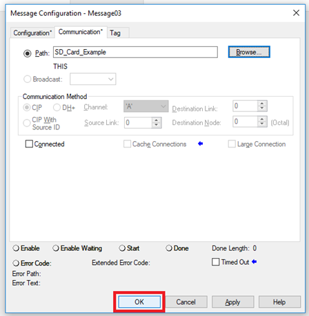
Step 8: Then click OK.
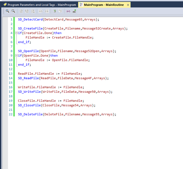
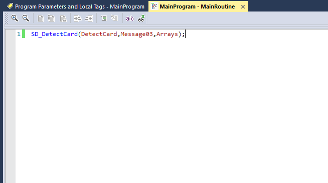
Step 9: You can now use the AOI by passing it with the SD_Arrays instance and the MESSAGE instance.
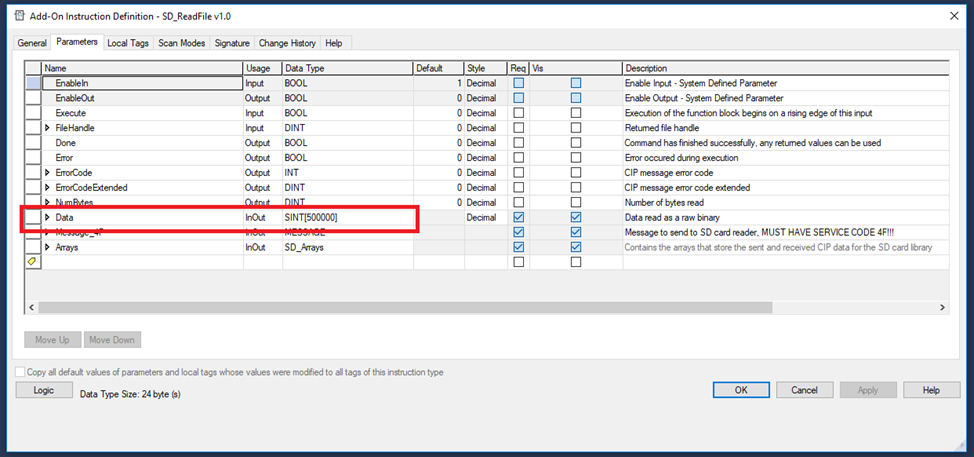
Step 10: The write and read instructions are limited by default to file sizes of up to 500,000 bytes. If larger file sizes are required, then this can be enabled by editing the size of the Data parameter of the write and read instructions. You can also reduce the size of the Data parameter to save memory if needed.
Step 11: VERY IMPORTANT NOTES:
Each different SD card AOI type requires a different Service Code for its MESSAGE parameter. Using a SD card AOI with a MESSAGE configured with the wrong Service Code will result in an error.
Each SD card AOI instance requires its own separate MESSAGE parameter. Using the same MESSAGE for multiple AOI instances will result in an error.
The SD_Arrays parameter can be reused for multiple AOI instances. However, you must take care to avoid executing multiple SD card AOIs simultaneously with the same SD_Arrays parameter. Doing so will result in unexpected behavior.
The meanings of the error codes and the extended error codes can be found in the Logix 5000 Controllers General Instructions (Publication 1756-RM003V-EN-P) in Chapter 4 Input/Output in the Message Error Codes section.