Library Setup
Creating a new project
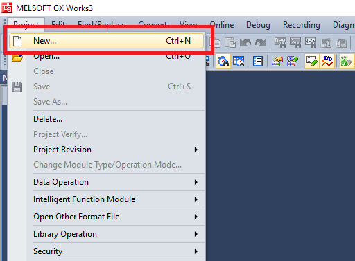
Step 1: Click on Project->New
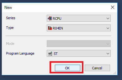
Step 2: In the New Project window select the Controller Series, Controller Type, and Program Language. Then click "OK"
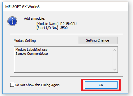
Step 3: Click "OK" in the Add Module dialogue window
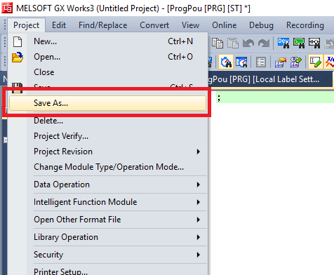
Step 4: To name the project, you will have to save the project. Click Project -> Save As
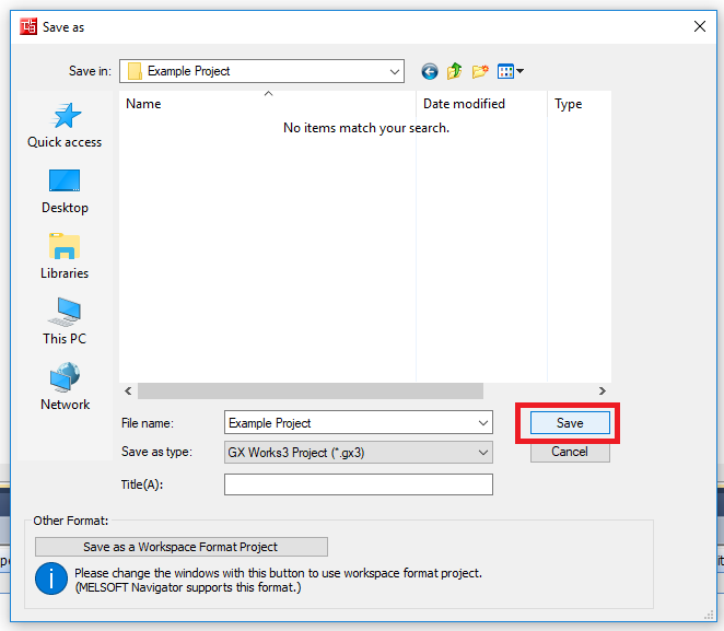
Step 5: Navigate to the directory where you want to store the project. Give the project a file name then click Save
Setup Fieldbus
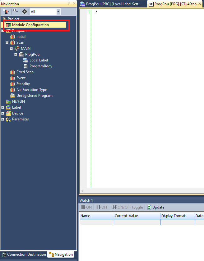
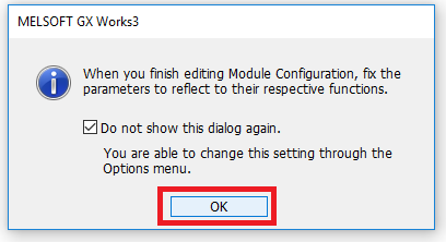
Step 1: Double click Module Configuration in the Navigation window. Click OK in the pop up window.
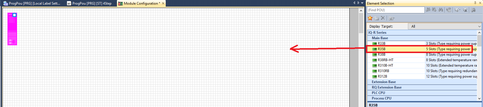
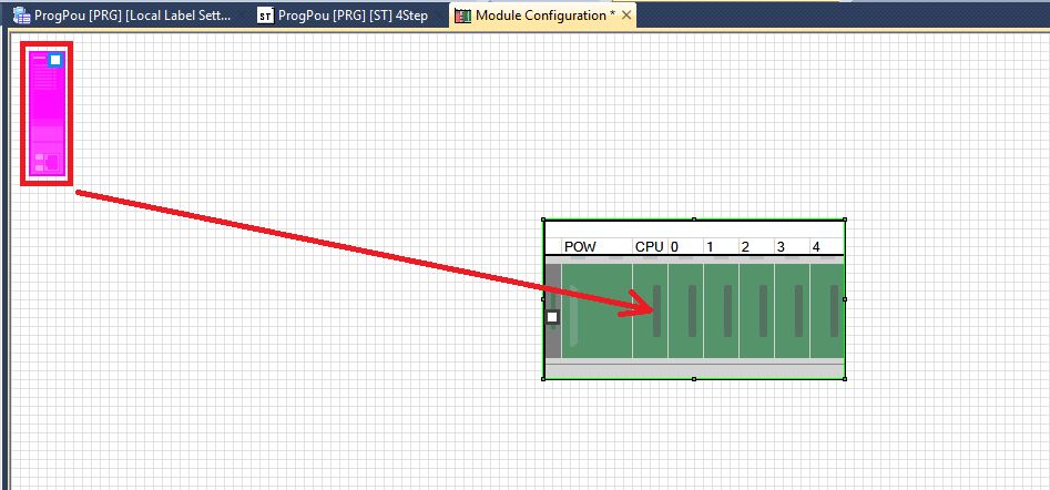
Step 2: Drag and drop the backplane unit you are using into the workspace. Then drag the CPU module into the CPU slot on the backplane
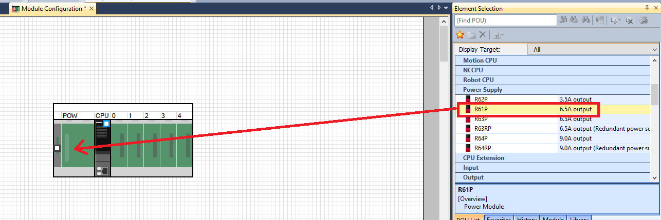
Step 3: Drag and drop the power supply you are using into the POW slot on the backpane.
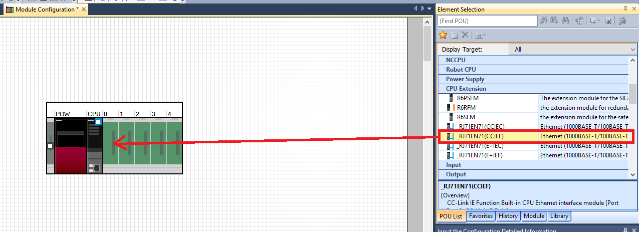
Step 4: Only if you are using a CPU module with a built in CC module. Drag and drop any of the _RJ71EN71 CPU extension units into the expansion slot next to the CPU slot
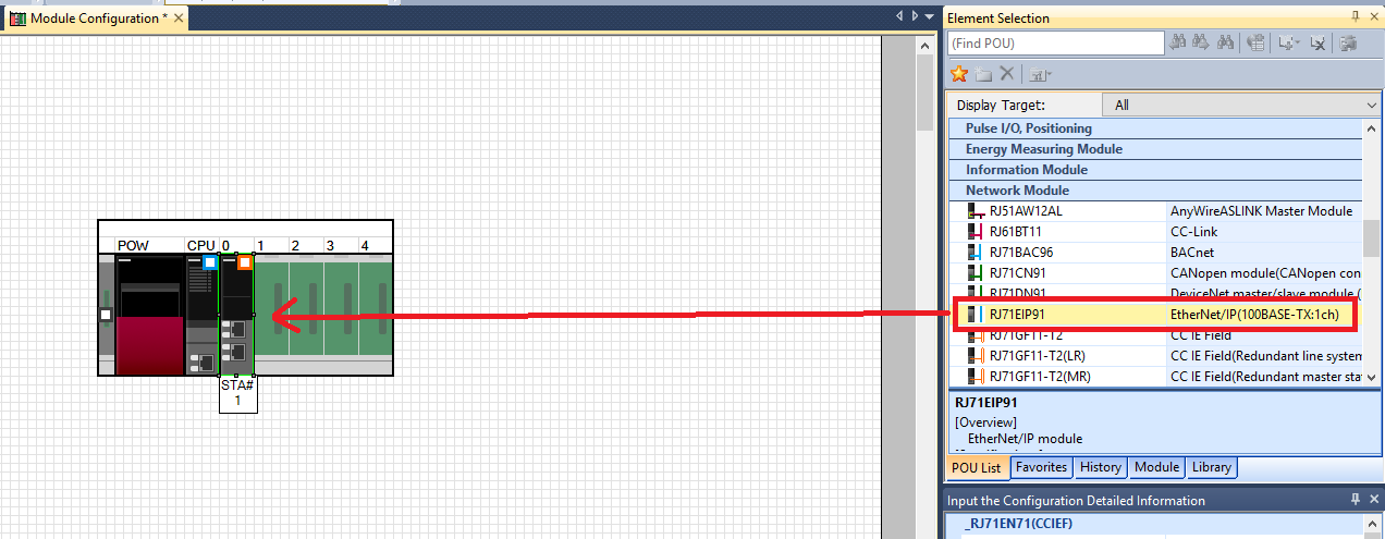
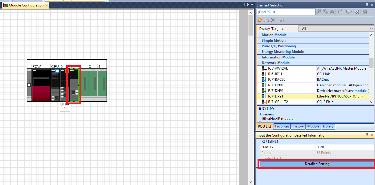
Step 5: Drag and drop the RJ71EIP91 EtherNet/IP Network Module onto the expansion slot that it is mounted to.
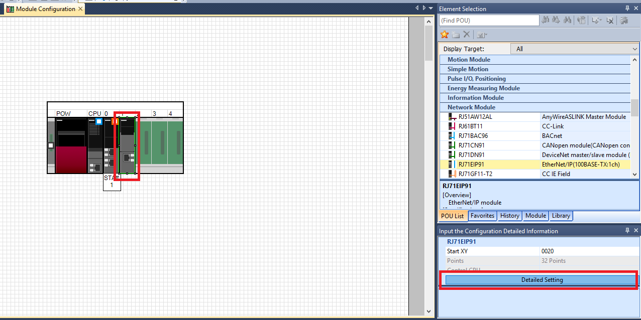
Step 6: Open the Detailed Settings of the Ethernet/IP module
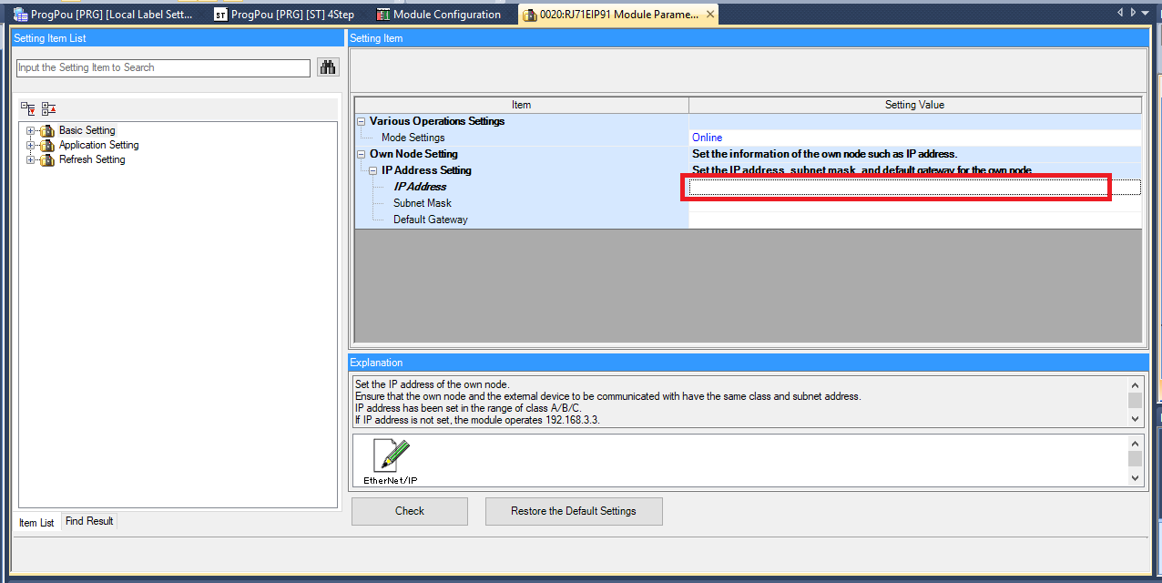
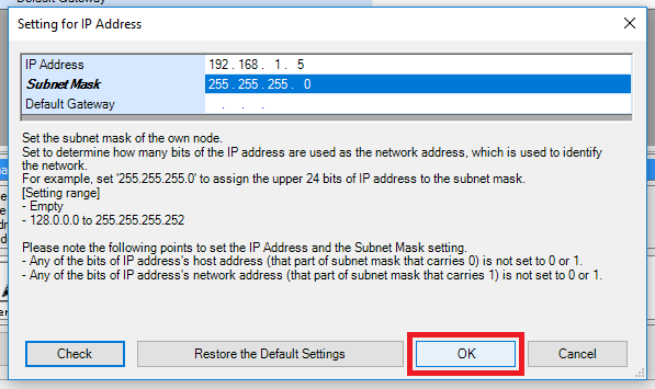
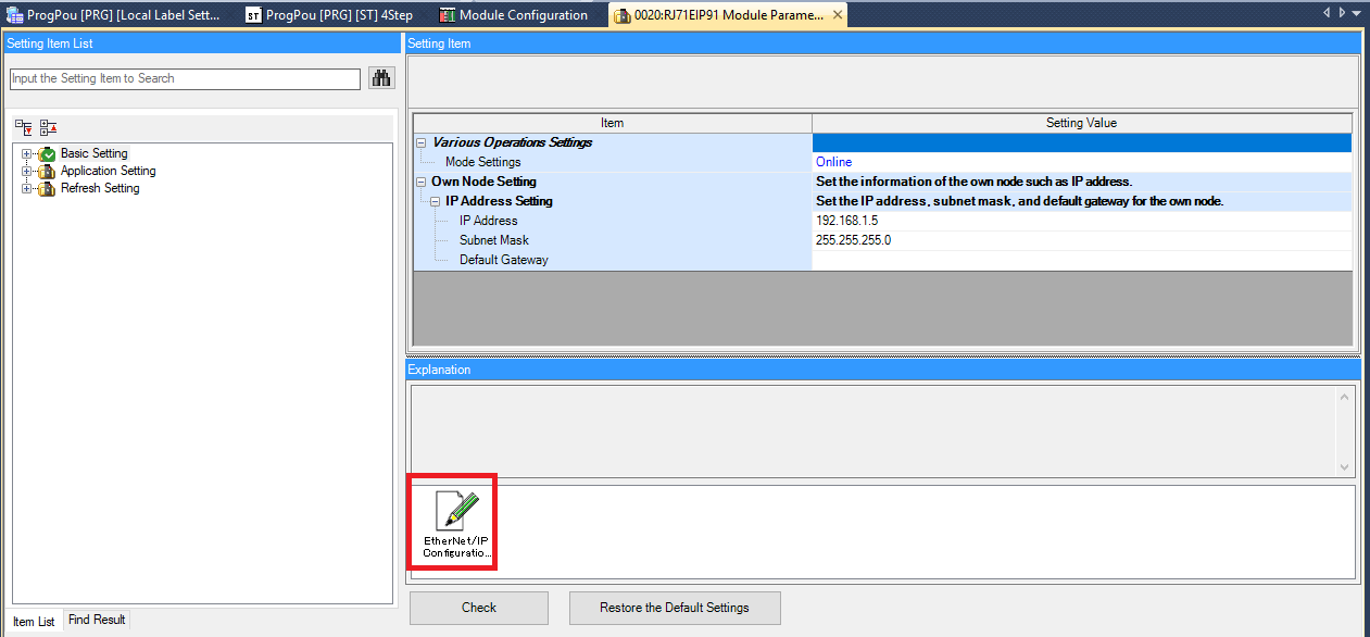
Step 7: Double click the IP Address setting to open the Setting for IP Address window. In the window set the IP Address and the Subnet Mask. Make sure that you can access this IP address! You will need to connect to the Ethernet/IP module to set the communication configuration.
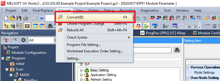
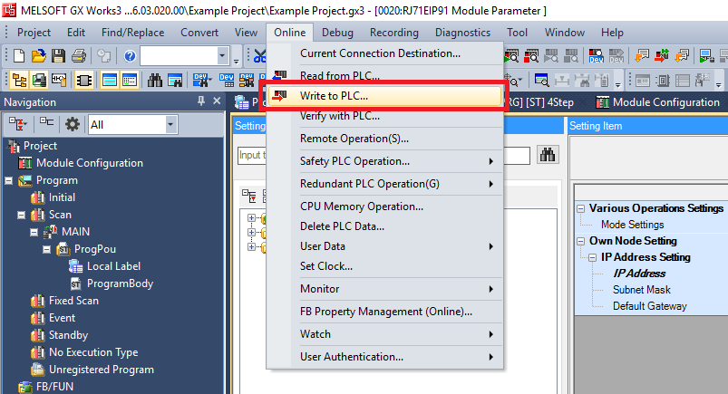
Step 8: Now you need to load the IP address setting to the Ethernet/IP module. Click Convert->Convert. Then click Online->Write to PLC
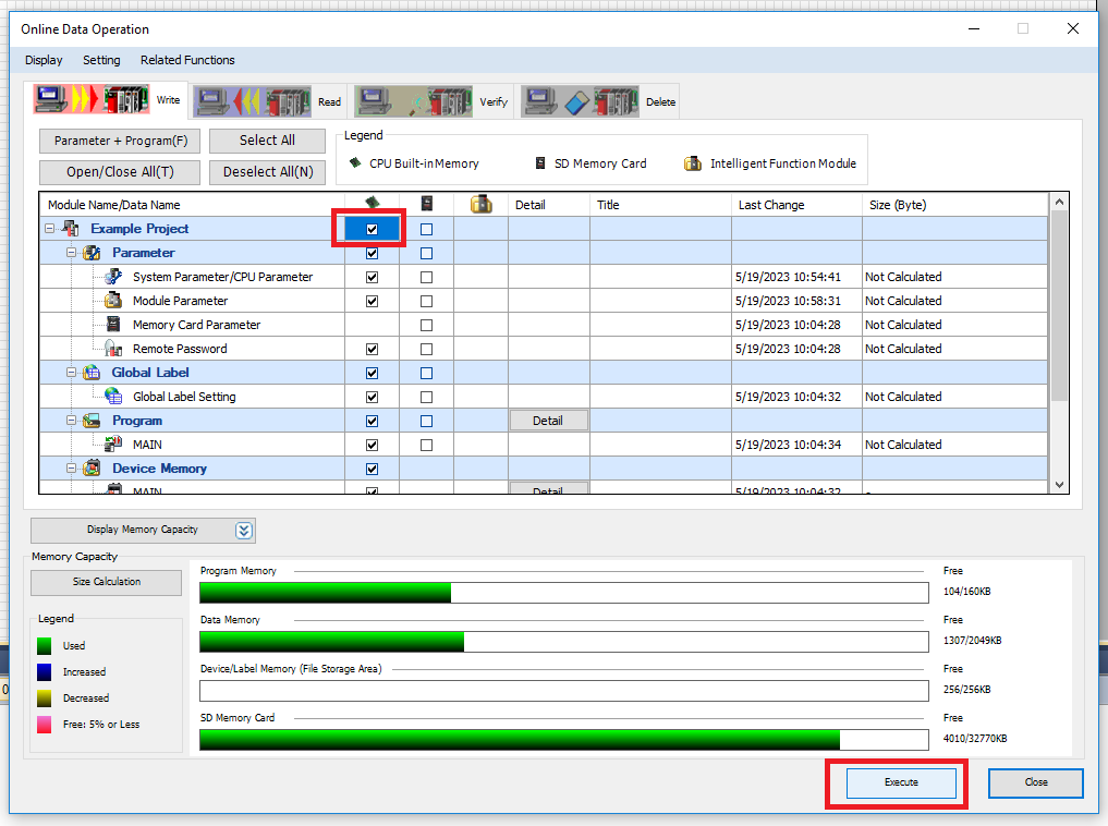
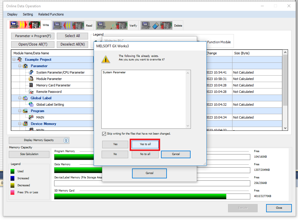
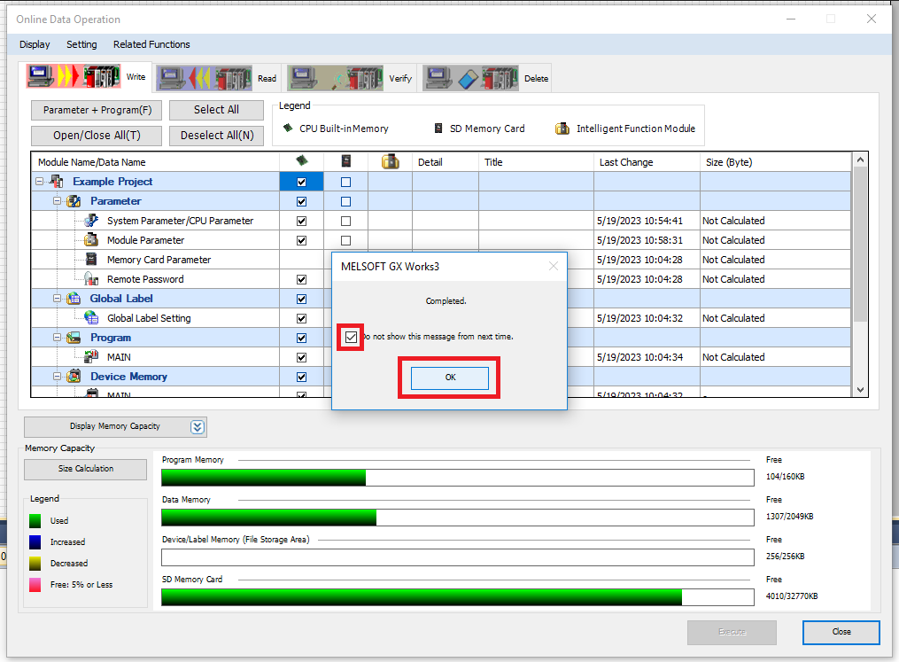
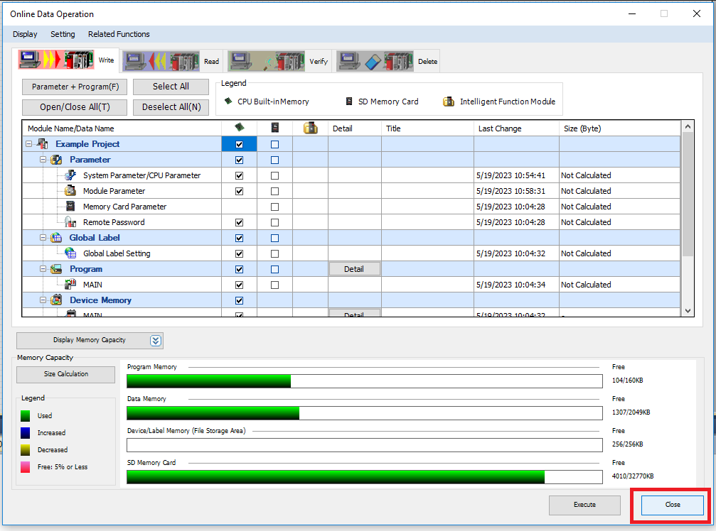
Step 9: Select the checkbox that chooses to write all the project files to the CPU built-in memory, then click Execute. Click Yes to all when it asks if you want to overwrite a file.
Step 10: Click OK when the transfer is completed, then click Close
Step 11: Go back to the Detailed Settings for the Ethernet/IP module. Open the EtherNet/IP Configuration Tool (this is a separate application that you will need to download and install from the Mitsubishi Electric website)
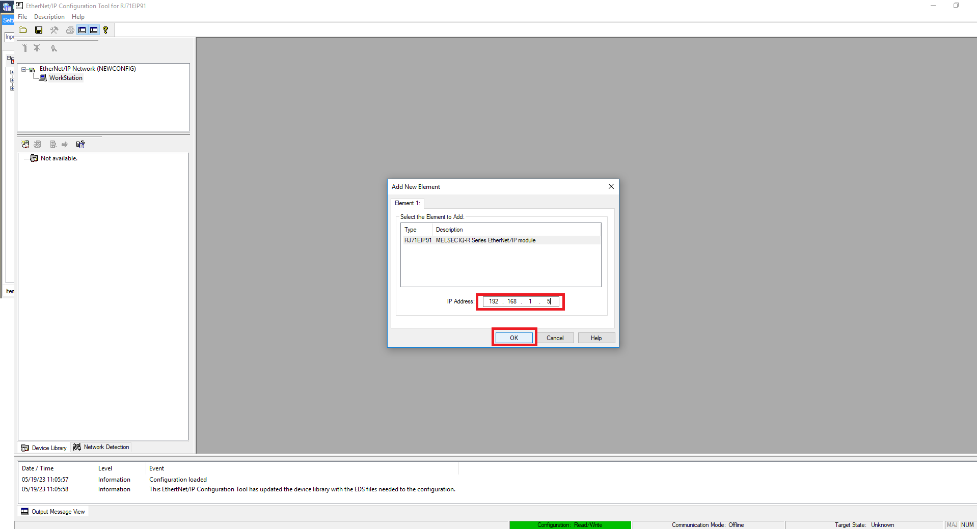
Step 12: In the Add New Element window of the Ethernet/IP Configuration Tool enter the IP address of the Ethernet/IP module and click OK
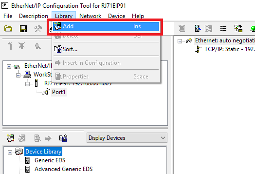
Step 13: If you haven’t used the PMC EDS file on this computer click Library->Add
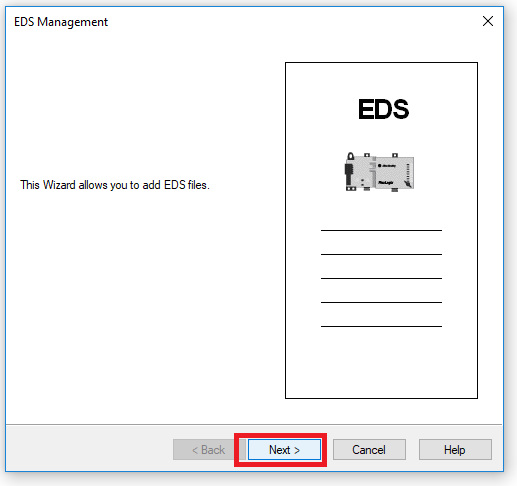
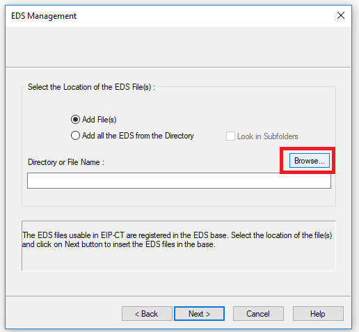
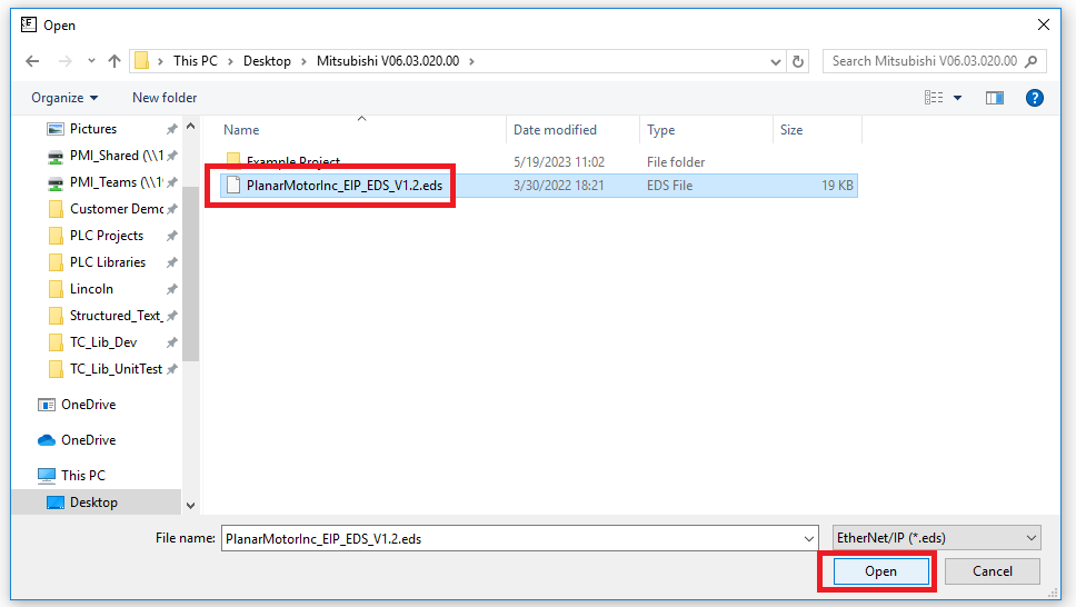
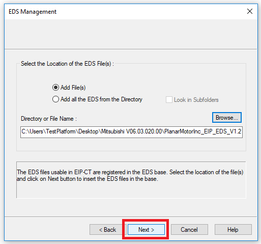
Step 14: Click Next on the opening screen. Then select Add File(s), then click Browse. Navigate to and select the Planar Motor EDS file. Then click Open
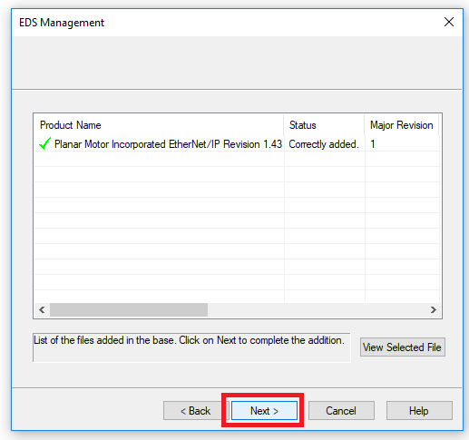
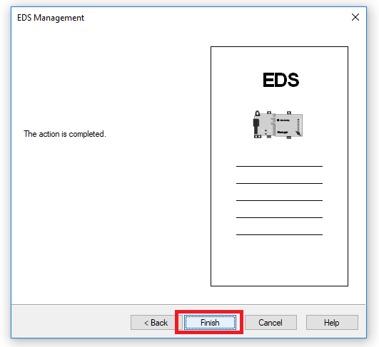
Step 15: Keep clicking Next until you reach the completion screen. Then click Finish
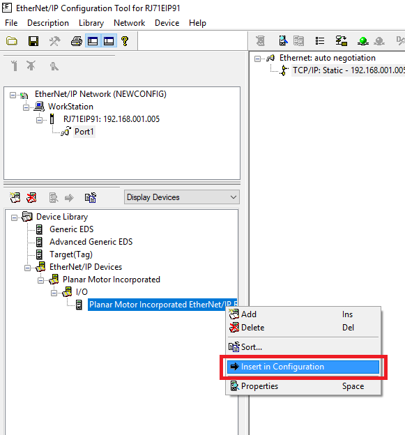
Step 16: In the Display Devices window find Device Library->EtherNet/IP Devices->Planar Motor Incorporated->I/O->Planar Motor Incorporated EtherNet/IP. Right click it and click Insert in Configuration
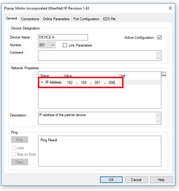
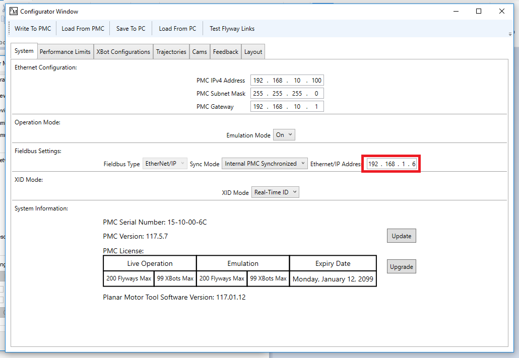
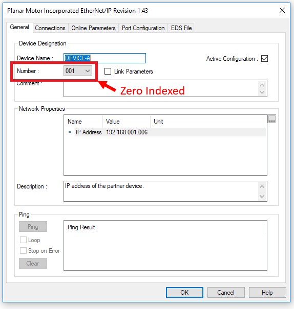
Step 17: Set the IP address setting in the EtherNet/IP Configuration Tool so that it matches the Ethernet/IP address set in the PMT configurator
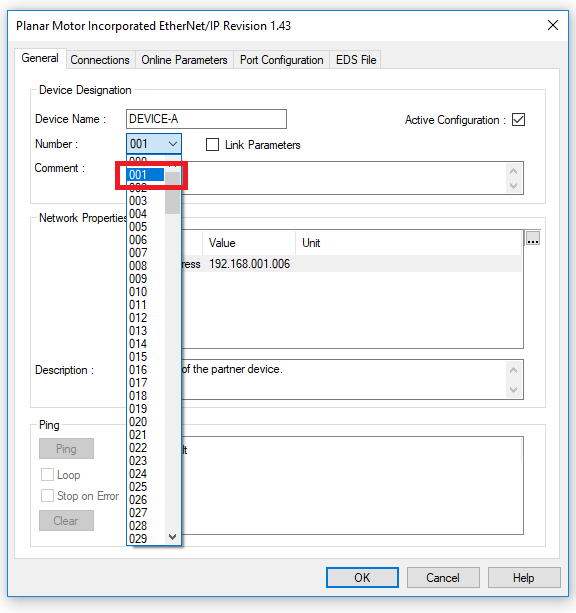
Step 18: Next set the Device Number. Note that the device number here is zero indexed. This will be important later when you are setting up the PMC library
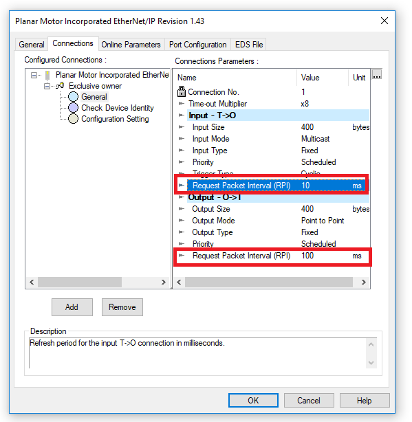
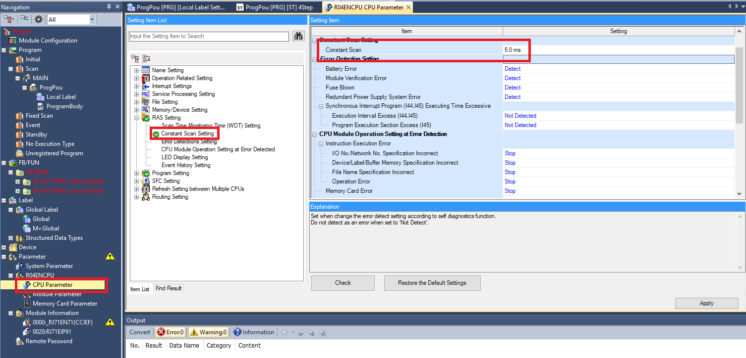
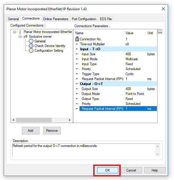
Step 19: In the Connections tab click Planar Motor Incorporated EtherNet/IP->Exclusive owner->General. Then set the Input and Output RPIs so that they are the same and <= to the Constant Scan setting of the CPU module
Step 20: Then click OK
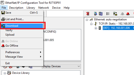
Step 21: Then click File->Go Online, then File->Download
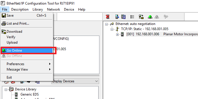
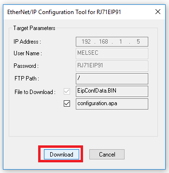
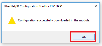
Step 22: Click Download in the pop up then OK
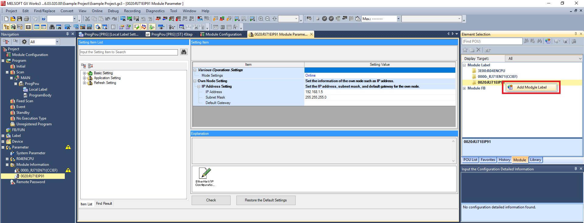
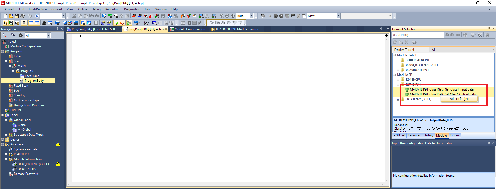
Step 23: In the Element Selection panel right click Module Label->RJ71EIP91 and click Add Module Label. Then select both the function blocks in Module FB->RJ71EIP91, right click then click Add to Project (note that when you are adding the FB you can’t be in the Module Parameters or Module Configuration windows)
Import and use library
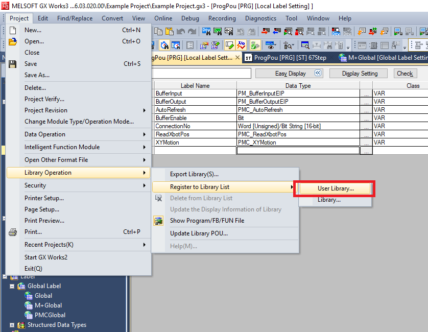
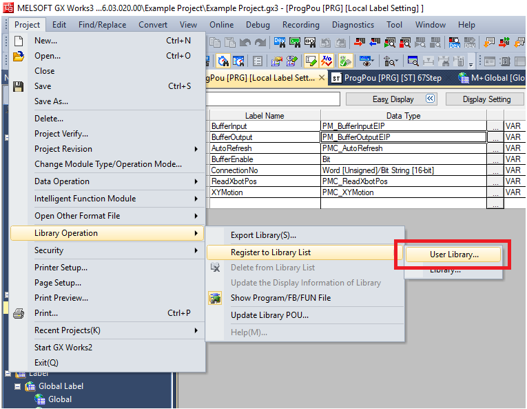
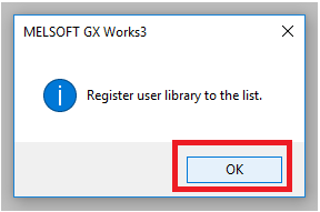
Step 1: Click Project -> Library Operation -> Register to Library List -> User Library. Then click OK in the pop up window
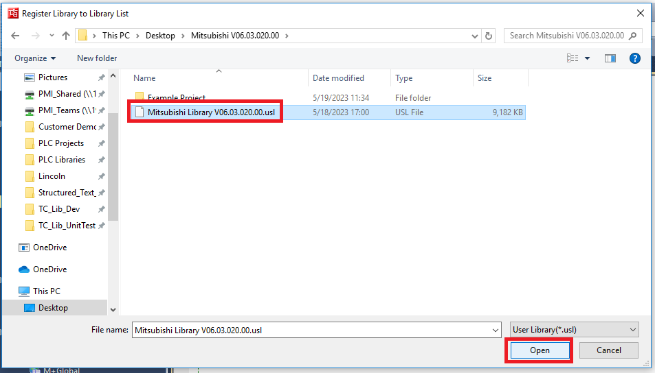
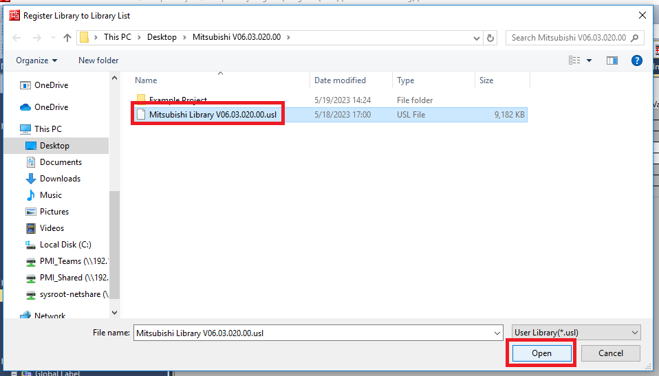
Step 2: Navigate to and select the PMC Mitsubishi Library .usl file. Click Open
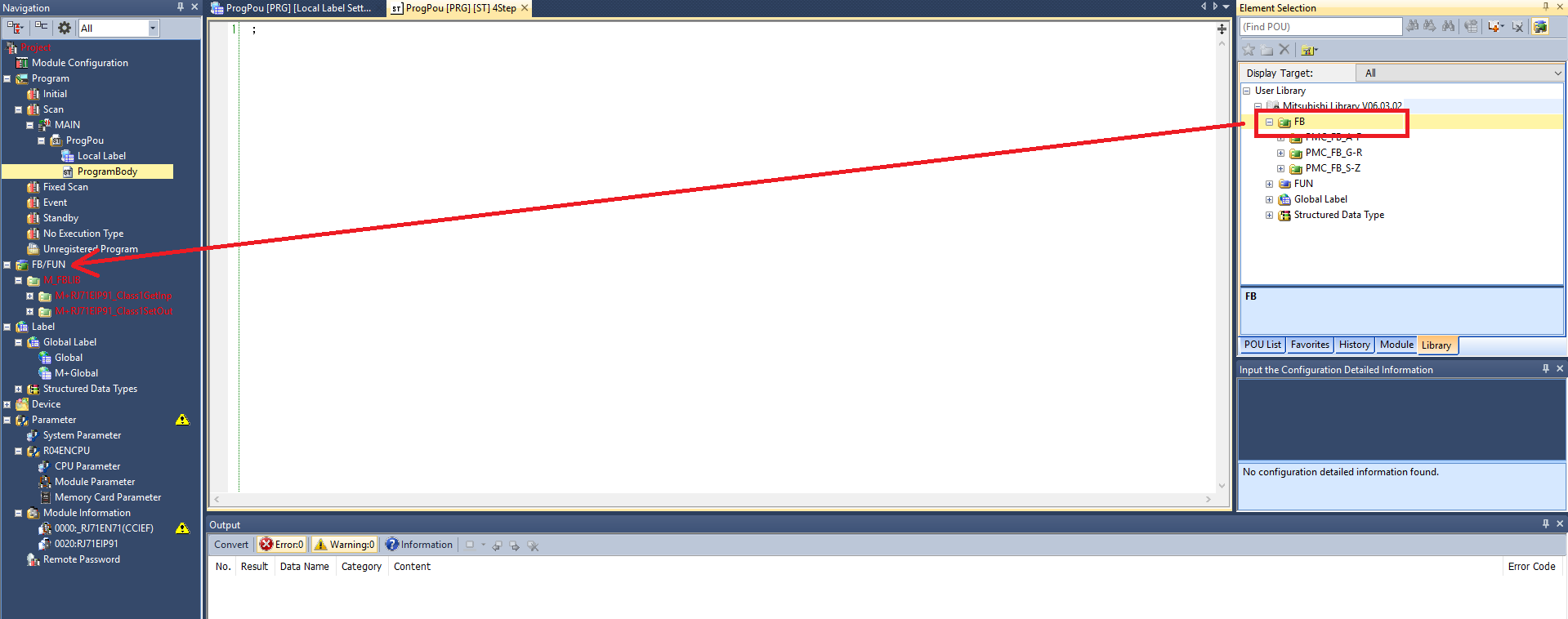
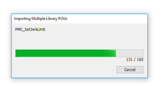
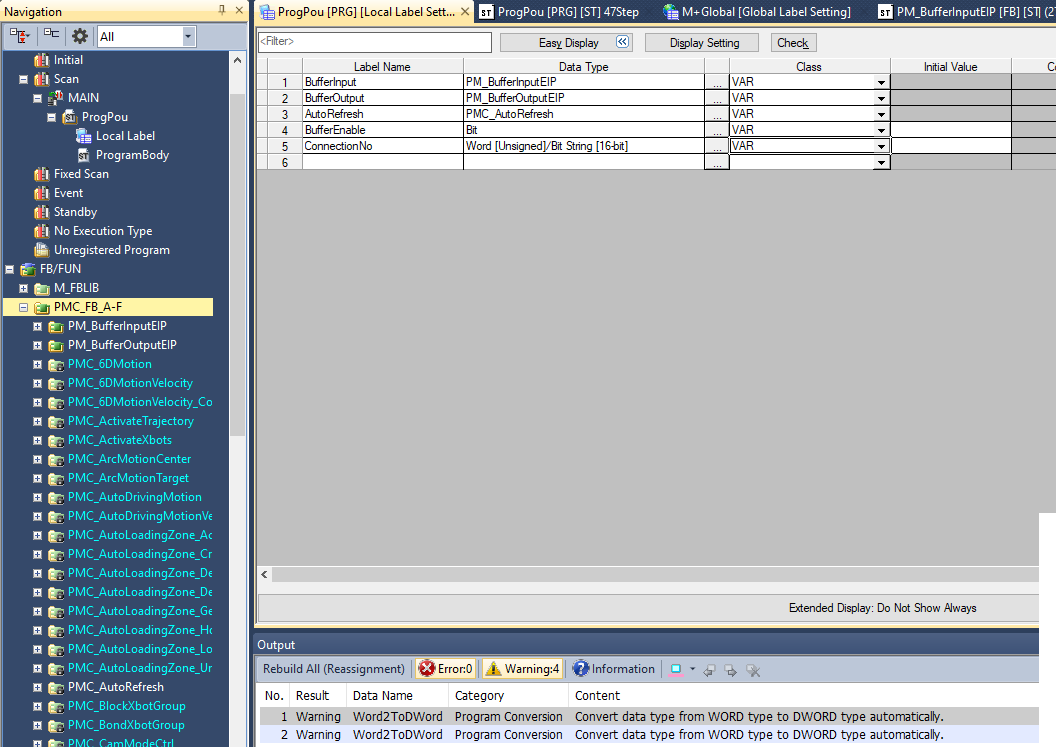
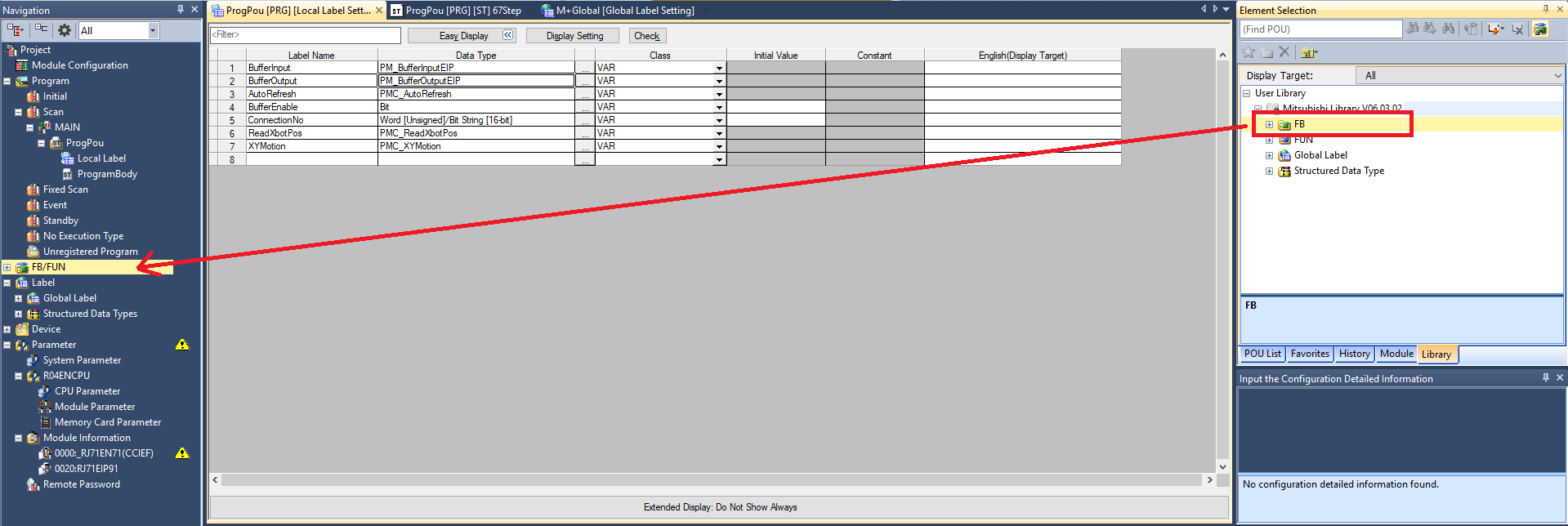
Step 3: In the Element Selection panel select the Library tab. Expand User Library -> Mitsubishi Library. Drag and drop the FB folder into the FB/FUN folder in the Navigation panel. This will automatically import over all the FBs, FUNs, Global Labels, and Data Types. The import progress will take multiple minutes
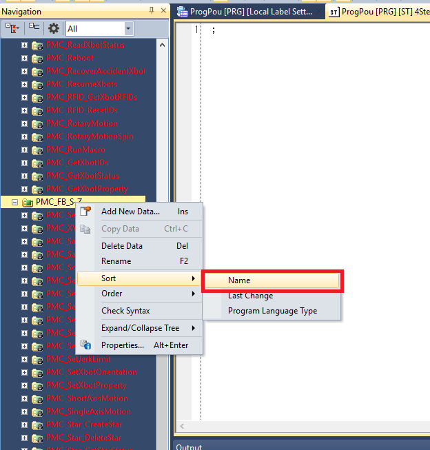
Step 4: It is recommended to sort the imported function block folders by Name since the import progress sorts them by last change
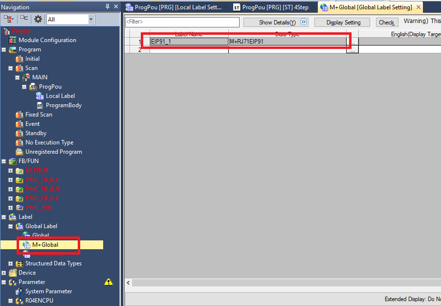
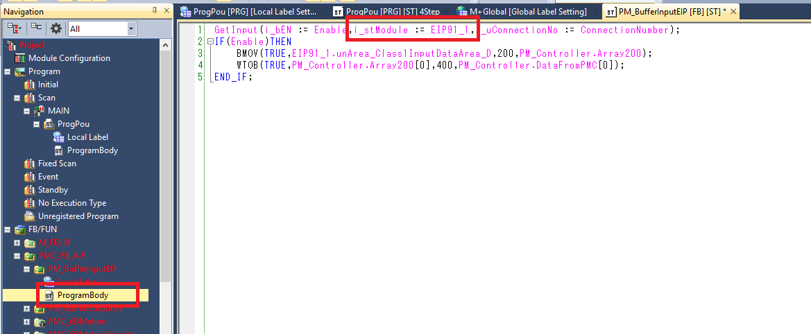
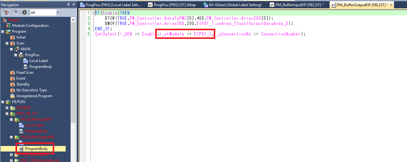
Step 5: Make sure that the M+RJ71EIP91 data type in the M+Global global variable list is named the same as the i_stModule variable used in PM_BufferInputEIP and PM_BufferOutputEIP
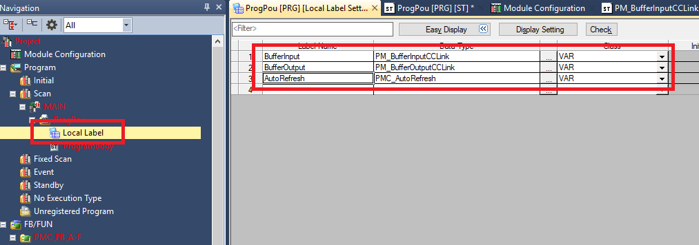
Step 6: In the Local Label of ProgPou declare one each of PM_BufferInputCCLink, PM_BufferOutputCCLink, and PMC_AutoRefresh function block variables
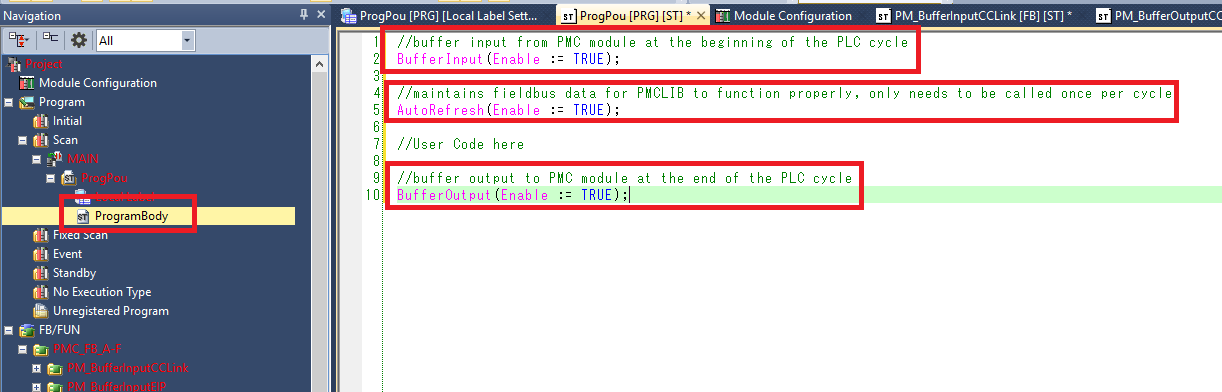
Step 7: In the ProgPou ProgramBody make sure the following is done:
-
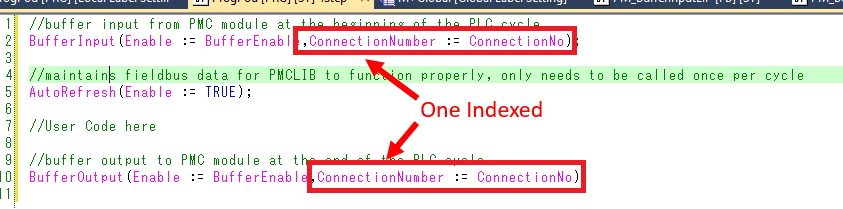
Call the PM_BufferInputCCLink function block once at the beginning of the PLC cycle
-
Call the PMC_AutoRefresh function block once and only once per PLC cycle. Make sure that the AutoRefresh call is after the BufferInput call and before the BufferOutput call.
-
Call the PM_BufferOutputCCLink function block once at the end of the PLC cycle
Step 8: The ConnectionNumber input used in PM_BufferInputEIP and PM_BufferOutputEIP is the device number set in the Ethernet/IP Configuration tool. However, the device number in the configuration tool is ZERO indexed while the ConnectionNumber in GX Works is ONE indexed. So in this case the ConnectionNo should be set to 2 to match the device number of 1.
This oddity is not caused by Planar Motor Inc. It is caused by the M+RJ71EIP91_Class1GetInput/SetOutput function blocks that have been created by Mitsubishi.
Step 9: If you encounter the following error message when trying to write a converted project to the controller.
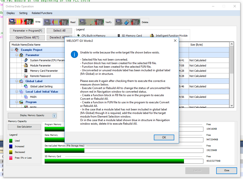
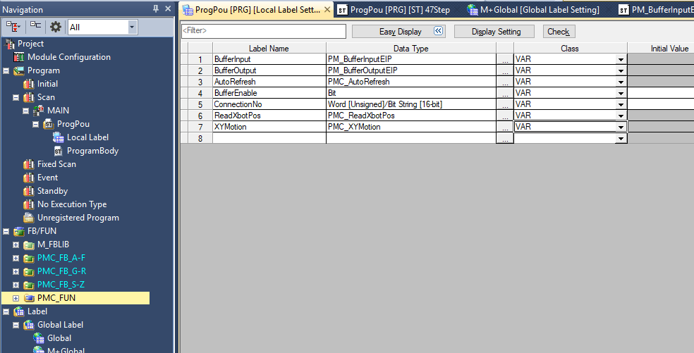
Step 10: It is because you have a FB/FUN folder that is not used in the project. For example, here I am only using stuff from the PMC_FB_A-F, and PMC_FUN folders (AutoRefresh uses stuff from PMC_FUN). So the error is because I am not using anything from PMC_FB_G-R and PMC_FB_S-Z folders
Step 11: You can correct this error by either deleting the unused folders or by using items from the unused folders. Here I have added PMC_ReadXbotPos from G-R and PMC_XYMotion from S-Z. This resolved the error and I was able to write the project to the PLC.
Upgrade Library
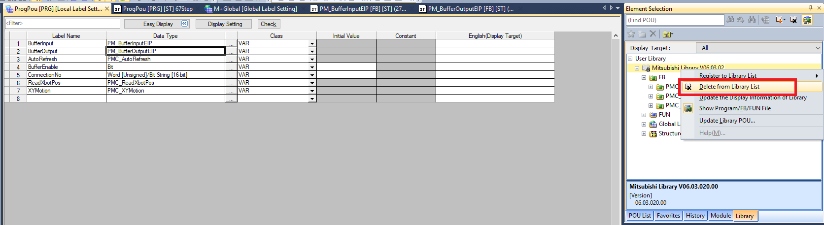
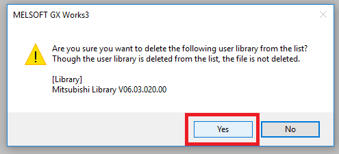
Step 1: In the Library tab of the Element Selection window Right click the old PMC Library folder and select Delete from Library List. Click Yes in the confirmation window
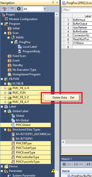
Step 2: Delete all the PMC FB/FUN folders, the PMCGlobal Global Label file, and all the PMC structured data types
Step 3: Click Project -> Library Operation -> Register to Library List -> User Library. Click OK
Step 4: Navigate to and select the new PMC library .usl file. Then click Open
Step 5: In the Element Selection panel select the Library tab. Expand User Library->Mitsubishi Library. Drag and drop the FB folder into the FB/FUN folder in the Navigation panel. This will automatically import over all the FBs, FUNs, Global Labels, and Data Types. The import progress will take multiple minutes
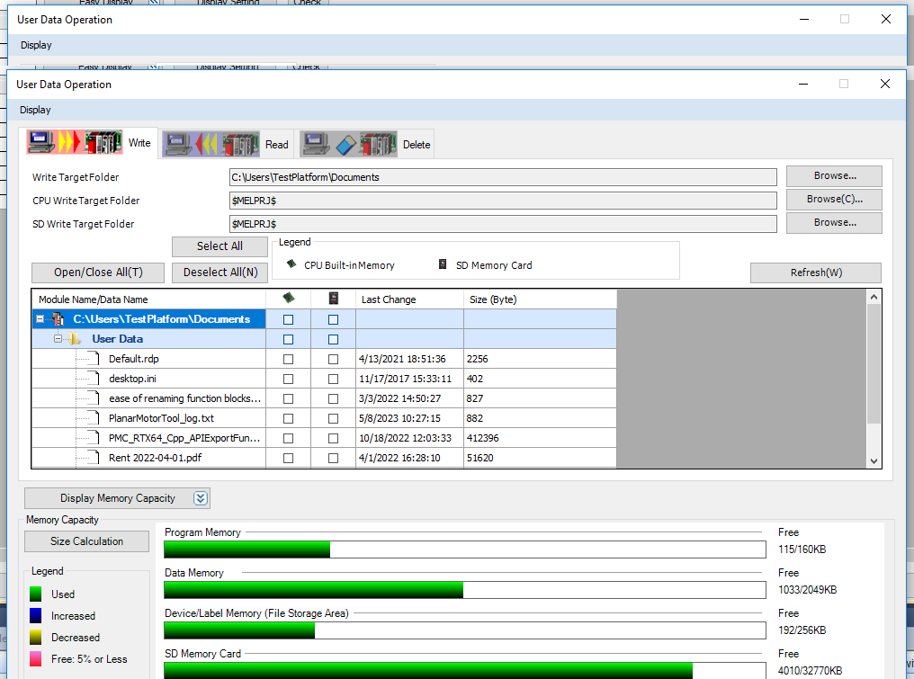
File I/O on the PLC (Optional)
The following is one possible way to read and write files to the PLC storage. It could be helpful for commands such as Set PMC Configuration.
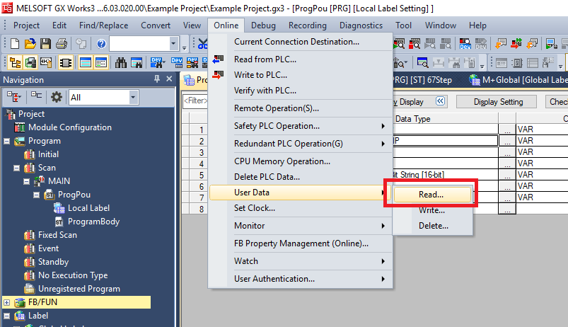
Step 1: Click Online -> User Data -> Read/Write/Delete
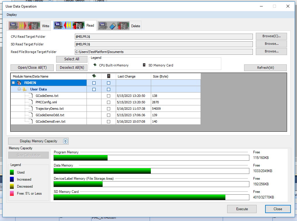
Step 2: In the Read tab you can select which files on the controller you wish to download to the computer. Read FileStorage TargetFolder is the directory where the selected files will be saved
Step 3: In the Write tab you can select which files on the computer you wish to download to the controller. WriteTargetFolder is the directory on the computer from which you can select the files to load onto the controller