
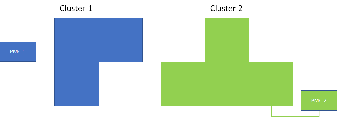
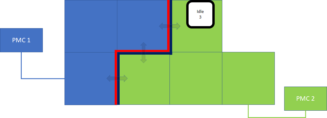
In this example, we will link two small clusters together (shown below). Cluster 1 (in blue) has 3 flyways, and cluster 2 (in green) has 4 flyways. Both systems are using Absolute ID, see XBot ID Management section for set up guide.
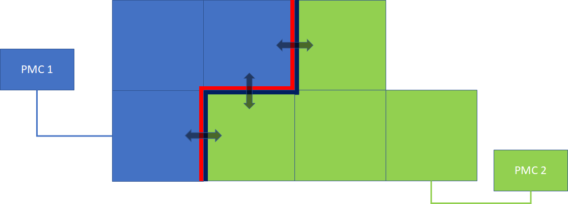
Step 1: configure each cluster with border
-
First, read and gain a basic understanding of the border concept and its limitation from Flyway Cluster Linking's border section.
-
Then, follow the Cluster Border Configuration to get both cluster 1 and cluster 2 ready for linking.
-
Next, establish physical connections for all borders configured in the previous step; see Electrical Setup for connection detail.
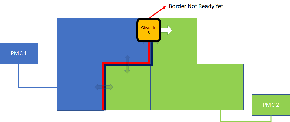
Step 2: Sending XBots out of the cluster
On PMC 1, use command Get Border Status to check if the border is in "Ready" state. Once the border is ready, use XY Motion to drive XBot to the neighbor system by specifying a coordinate OUTSIDE of the current system. If the border is not ready yet, XBot will enter "Obstacle" state when its center hits the border:
Once the border is in "Ready" state, XBot will resume its motion:
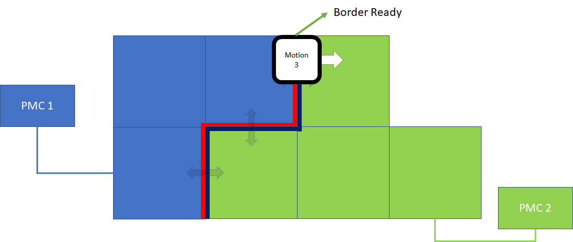
Step 3: Receiving XBots from Another cluster
Once the XBot's center passes the border, the control of XBot is handed to the neighbor cluster. In this example, XBot 3's control is handed to cluster "PMC 2".
On "PMC 2", you can call commands Read Number of Incoming XBots (Fieldbus only) and Get Incoming XBots to obtain a list of all XBots that enters the system through all borders, and start sending motion command to them. You might also want to call Get XBot Status to obtain the locations of incoming XBots, especially if the system is configured in Real-time ID mode. Read XBot ID Management section for more detail.