
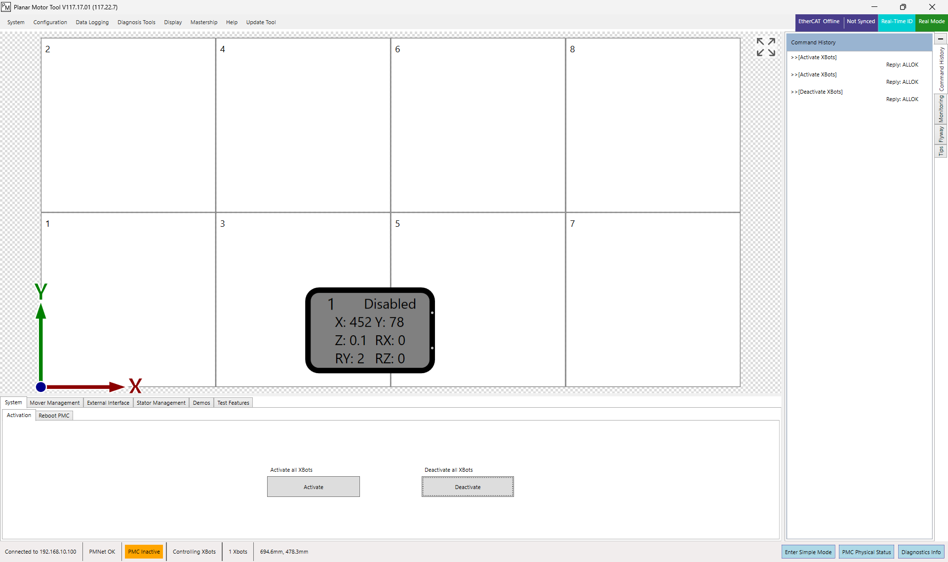
When the PMC (Planar Motor Controller) boots up correctly, the message “PMC Inactive” will be shown in orange at the bottom of the PMT (Planar Motor Tool) window.
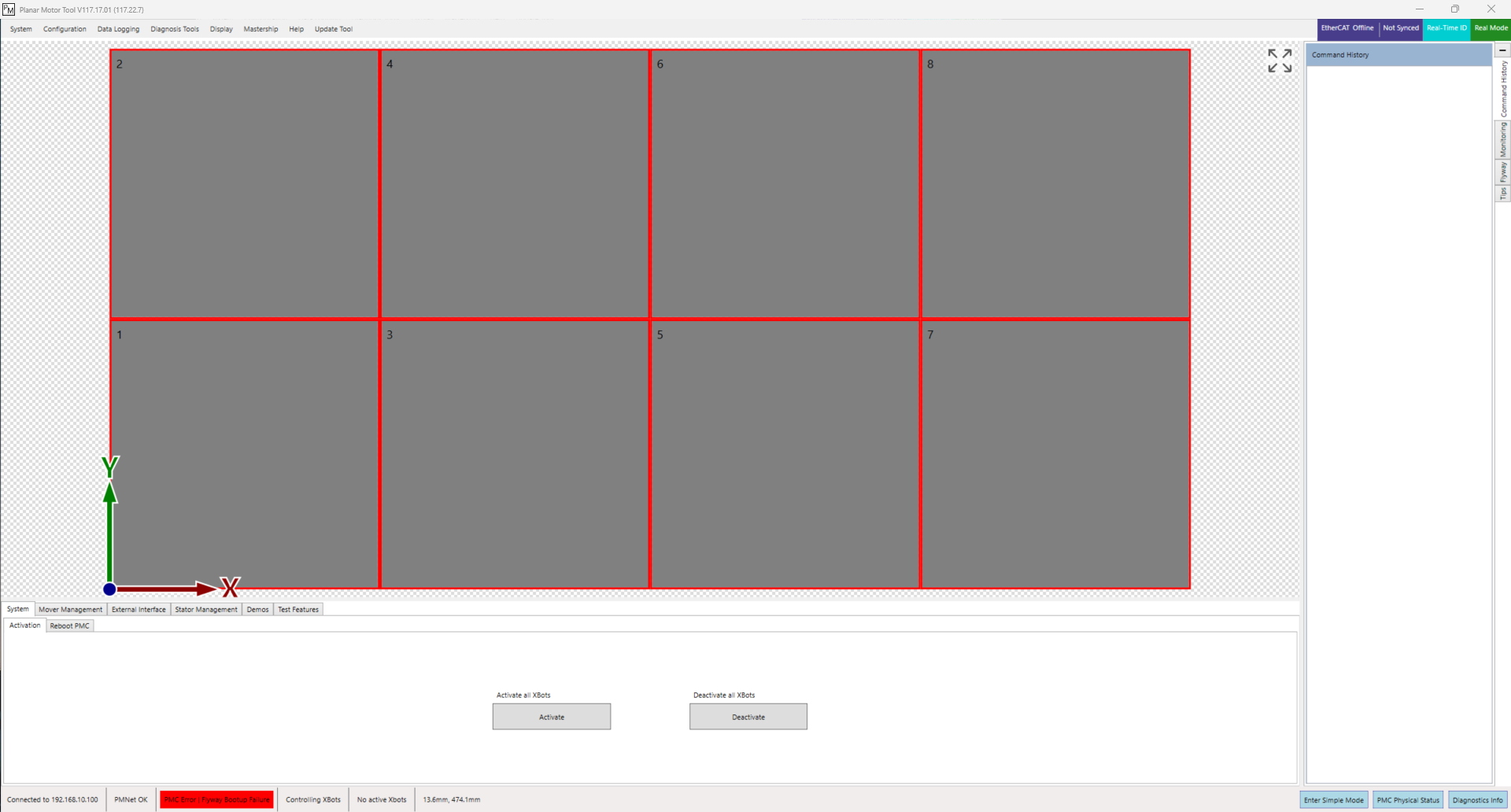
If the system fails to boot up, a common error you may see is “PMC Error | Flyway Bootup Failure”. Shown in red at the bottom of the PMT window.
This guide describes possible reasons and fixes for this error. The troubleshooting steps below should be followed in order. If at any point one of the steps is successful in fixing the error, you may skip the rest of the document.
If you need more help at any time please email support@planarmotor.com.
1. Power Cycle
As a first step, the flyways should be power cycled.
After a Flyway Bootup Error, the Flyways must be power-cycled before a new configuration can be applied. The steps in this guide may involve modifying the configuration to help resolve the error. Each time you write a new configuration to the PMC, you must power cycle the Flyways to allow them to reconnect using the updated settings. To do this, cut power to all the flyways, wait three seconds, and power them again.
How to save, change, and write a configuration to the PMC
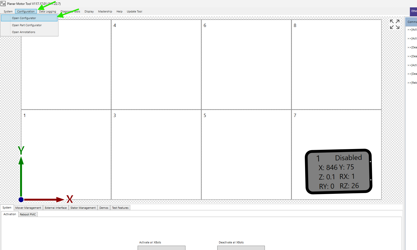
Open the configurator in PMT.
In the configurator tab, you can make modifications to several aspects of the system including system series, flyway layout, xbot types, home positions, etc. If you wish to save the current configuration as a back up before making any changes, you can do so using the button in the image below.
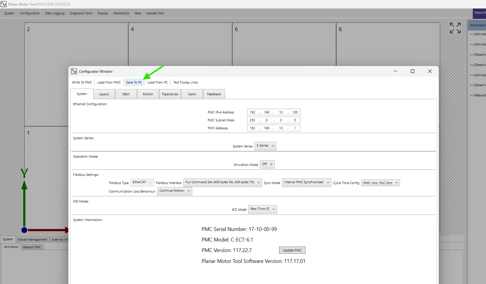
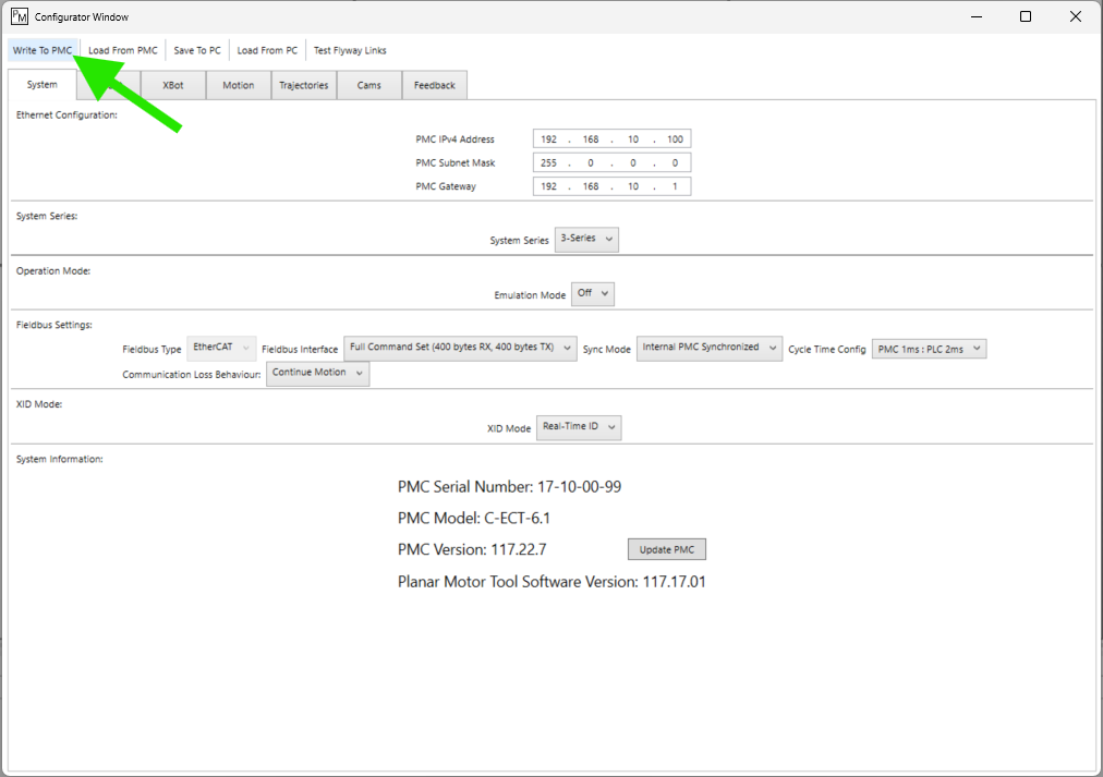
After you modify the configuration, you must write it to the PMC for it to take effect. Click the button shown in the image below. After it is written, the PMC will reboot. After the reboot finishes, you may need to power cycle the flyways.
2. Fix Differences Between the Configured Layout and the Real Layout
If the layout entered in PMT is different from the physical system, it will not boot up. Look through the following common mistakes and change your configuration to fix them if needed.
2.1. X and Y Dimensions
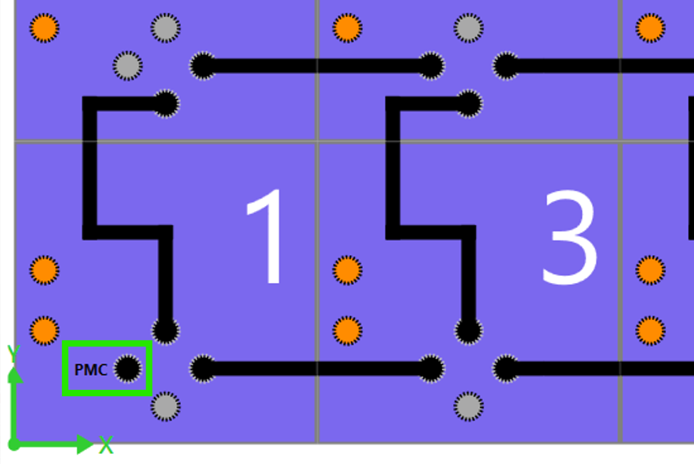
The X and Y dimensions, as well as the positions of all flyways in the system, must be set correctly. Since the top surface of the flyways is feature-less, it is difficult to know their X and Y orientation. Looking at the flyways from underneath is more useful since the connectors allow you to see the orientation of the flyways. For a correct configuration, the wiring diagram in PMT must exactly match the physical system. Note that the default view shown in the wiring diagram is a top view, as if looking through the flyways.
How to view the wiring diagram
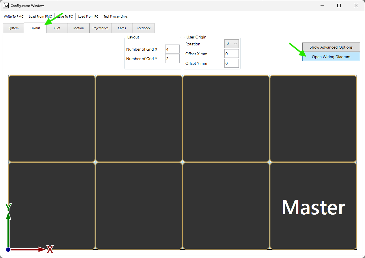
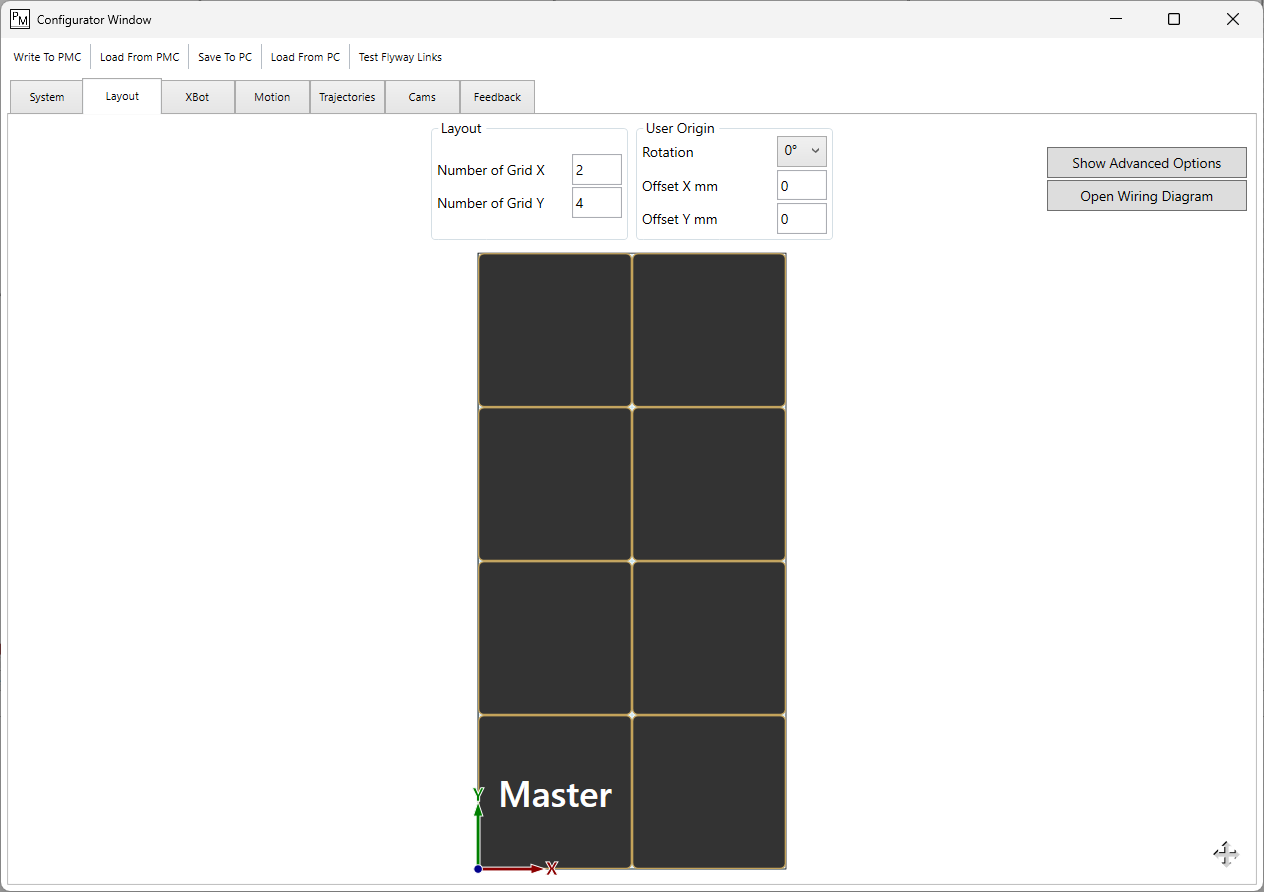
Open the configurator and go to the layout tab. Then click “Open Wiring Diagram”.
Click the Display button to toggle between flyways with different data connector types. Choose the one that matches your flyways.
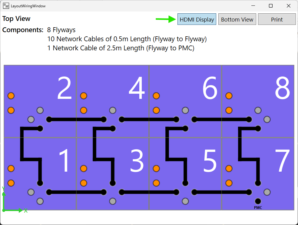
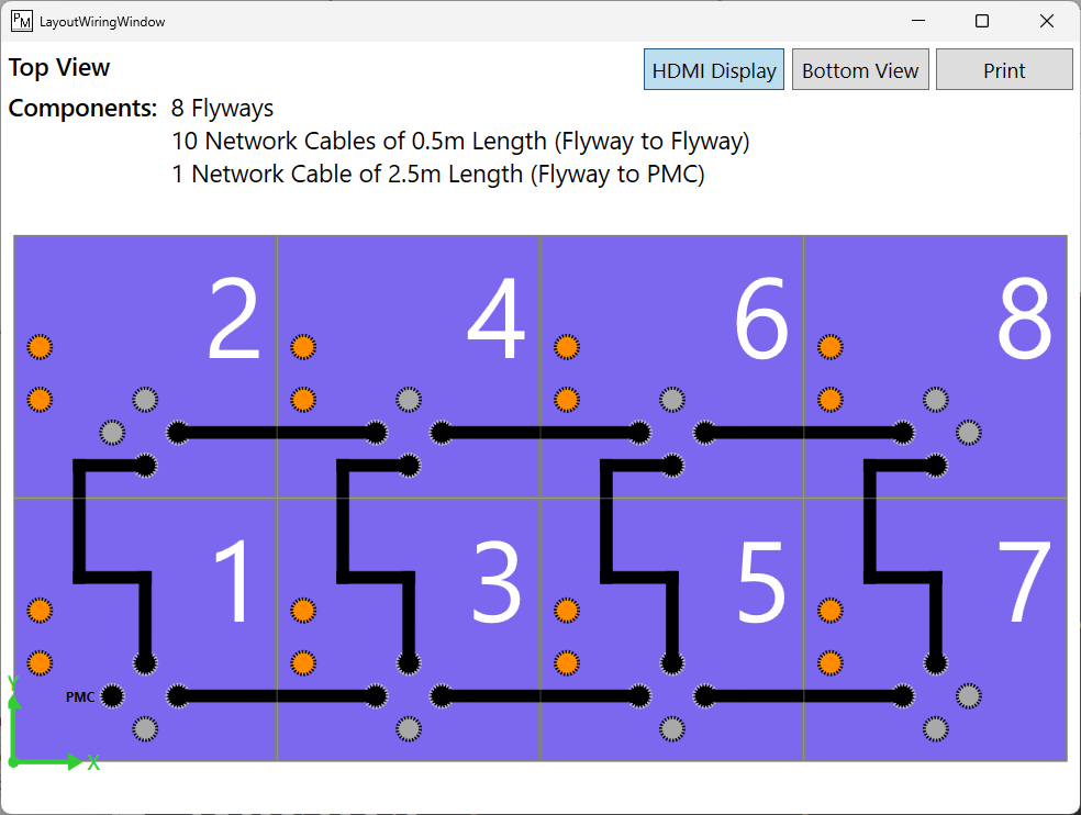
Example: It would be easy to get confused between a 4x2 and a 2x4 layout because they look identical from the top. You must look at the flyways from below to determine their orientation and make sure that the layout you configured in PMT matches your physical system. Noting the position of the orange power ports is specially helpful for determining the orientation of the flyway in relation to the layout.
4 by 2 flyway layout.
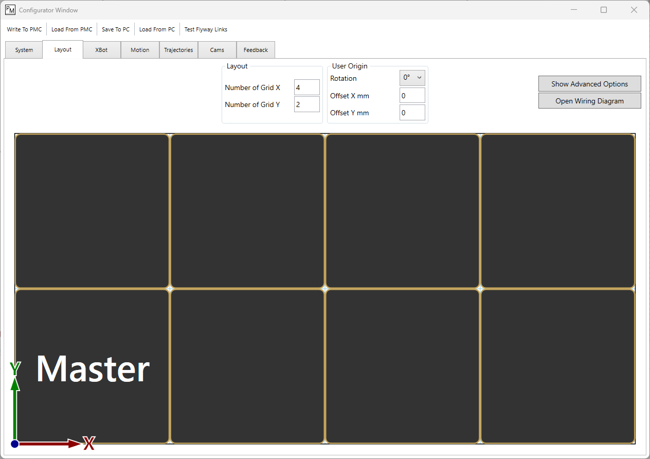
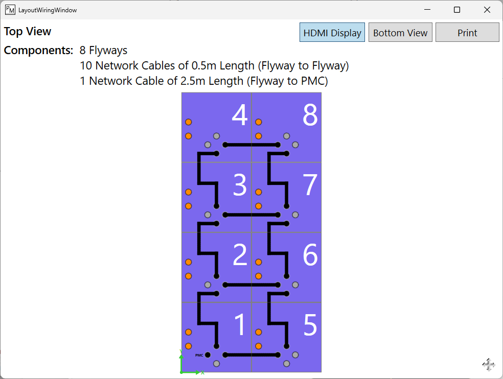
2 by 4 flyway layout
2.2. Master Flyway
The flyway that is directly connected to the PMC must be set as configured as the master flyway in PMT. As in the previous step, the wiring diagram can be used to verify orientation and ensure that the master flyway is set correctly. You may change the master flyway in PMT if needed.
How to set a different master flyway
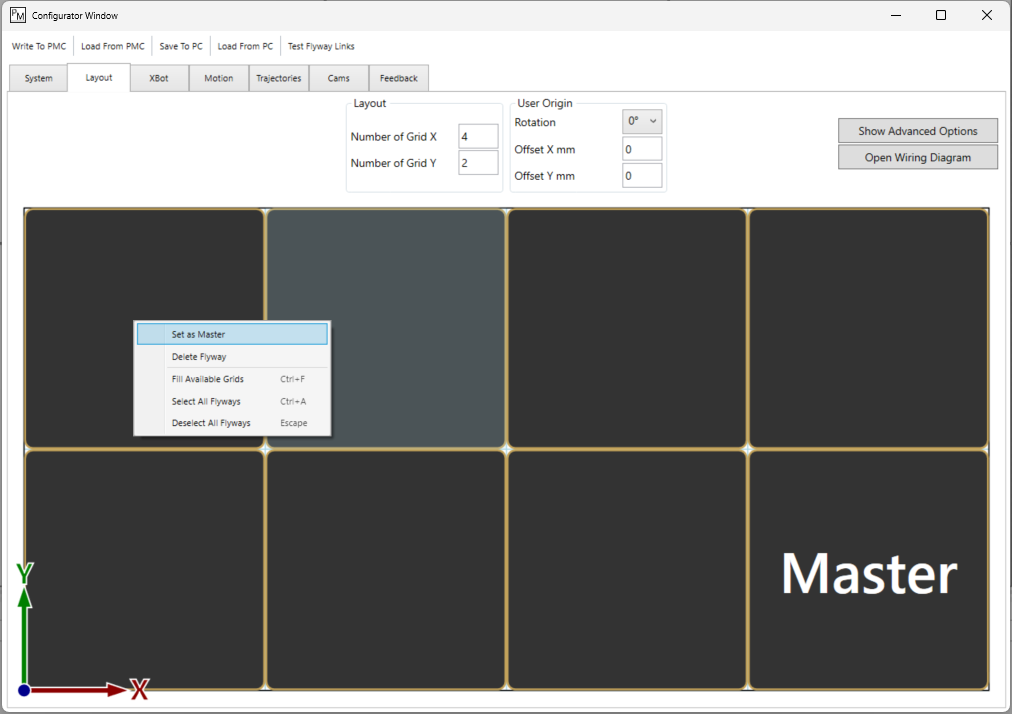
In the configurator, under the layout tab, right-click the desired flyway and select “Set as Master”.
In addition, the PMC must be connected to the master flyway via the port specified in the wiring diagram.
3. Check the Cabling
If the configuration matches the real layout, but the error persists, it is likely that one or many flyways are not connected to power or communication.
Verify that all the data cables in the real system are connected as specified in the wiring diagram in PMT. Make sure there are no loose connections.