This guide provides reference information to help customers design Flyway mounting solutions.
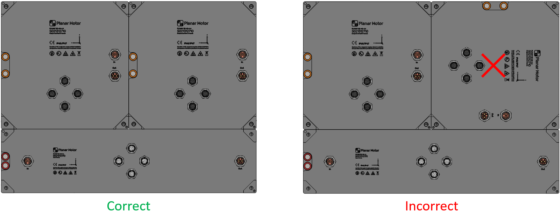
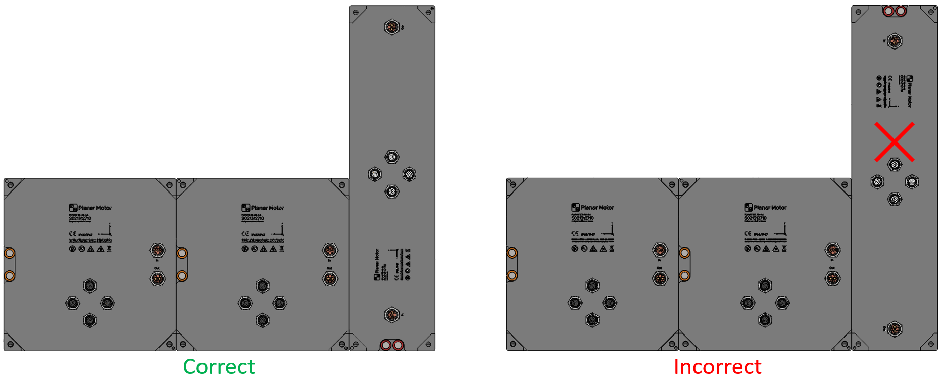
Flyway Spacing and Orientation
Important aspects to consider:
-
Pitch: Flyways should be mounted with a pitch based on increments of half their nominal size of 240 mm for S3 systems or 320 mm for S4 systems. Flyways are undersized 0.3mm to facilitate assembly.
-
Orientation: All Flyways must have the same Rz orientation. The laser-marked XY coordinate system on the bottom should match across all Flyways. The only exception to this rule is when an “xN” Flyway (a rectangular one) is oriented along the Y-axis. In this case, its positive Y-axis should point in the direction of the other Flyways' positive X-axis.
-
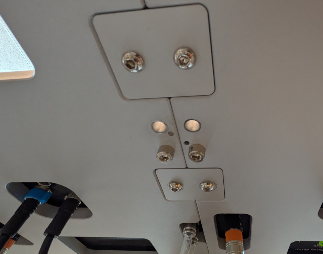
Alignment: Good alignment ensures smooth motion when XBots travel between Flyways. Each Flyway has a hole and a slot in diagonally opposing corners for locating pins.
-
Misalignment: If smoothness of motion is not critical, it is often acceptable to forgo the dowel pins. There can also be a misalignment between Flyways of up to 0.5mm, but it will negatively impact the smoothness of motion when the XBot crosses between Flyways.
-
Mounting Plate Material: A common choice is aluminum plate 5-15mm thick. Since Aluminum is non-magnetic, it is safer to load/unload XBots without the risk of magnetic attraction to the mounting plate. However, a steel mounting plate will not affect normal operation of the system.
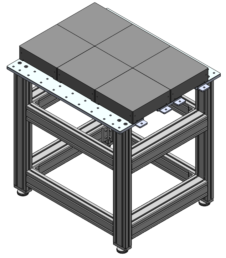
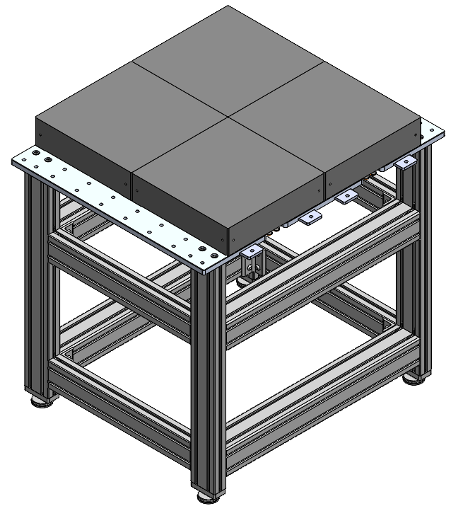
Modular Mounting Table Design
Sizing: The table should be sized to the nominal footprint of the Flyways. For example, a table for 2×2 S4-xS Flyways should be 640×640 mm. This ensures the Flyways will be at the correct distance and won’t hit each other when bringing two tables together.
Leveling: Modular tables should have adjustable leveling features to ensure they can be made coplanar. Typically height adjustable feet for the table are used to achieve this.
Joining tables: There are many ways to join the tables together. Toggle latches; dowel pins and holes; and machined mating features have all been used successfully. The solutions below are just examples.
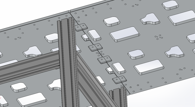
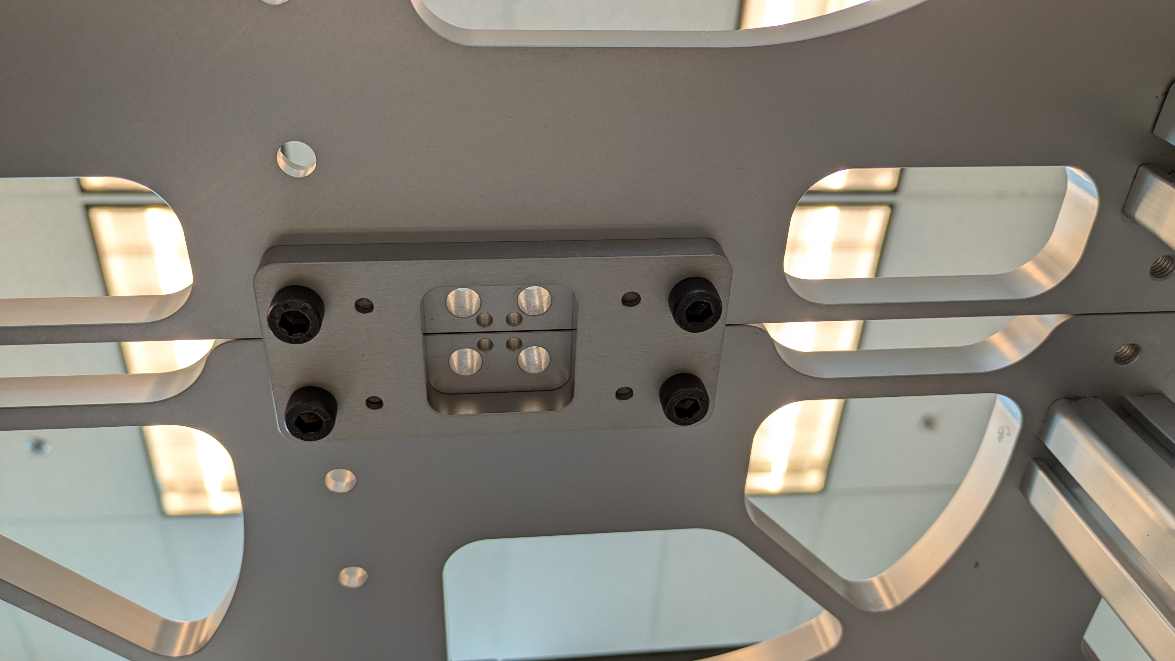
Machined pockets and coupling plates
-
The mounting plates have machined pockets on each end, with threaded holes.
-
When the tables are placed together, the pockets align and are connected using small coupling plates that sit in the pockets.
-
The coupling plates have clearance holes and are held in place by screws.
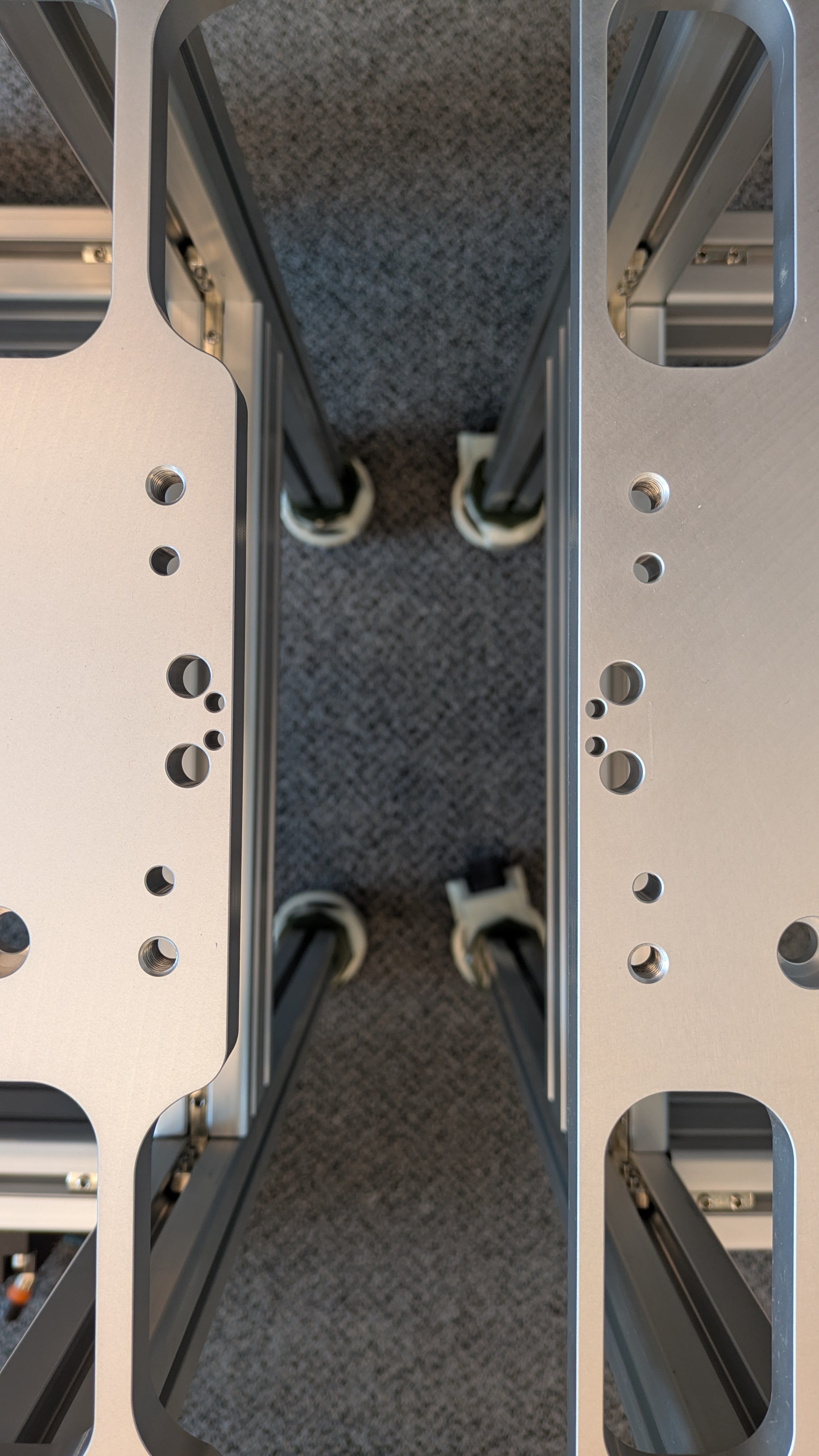
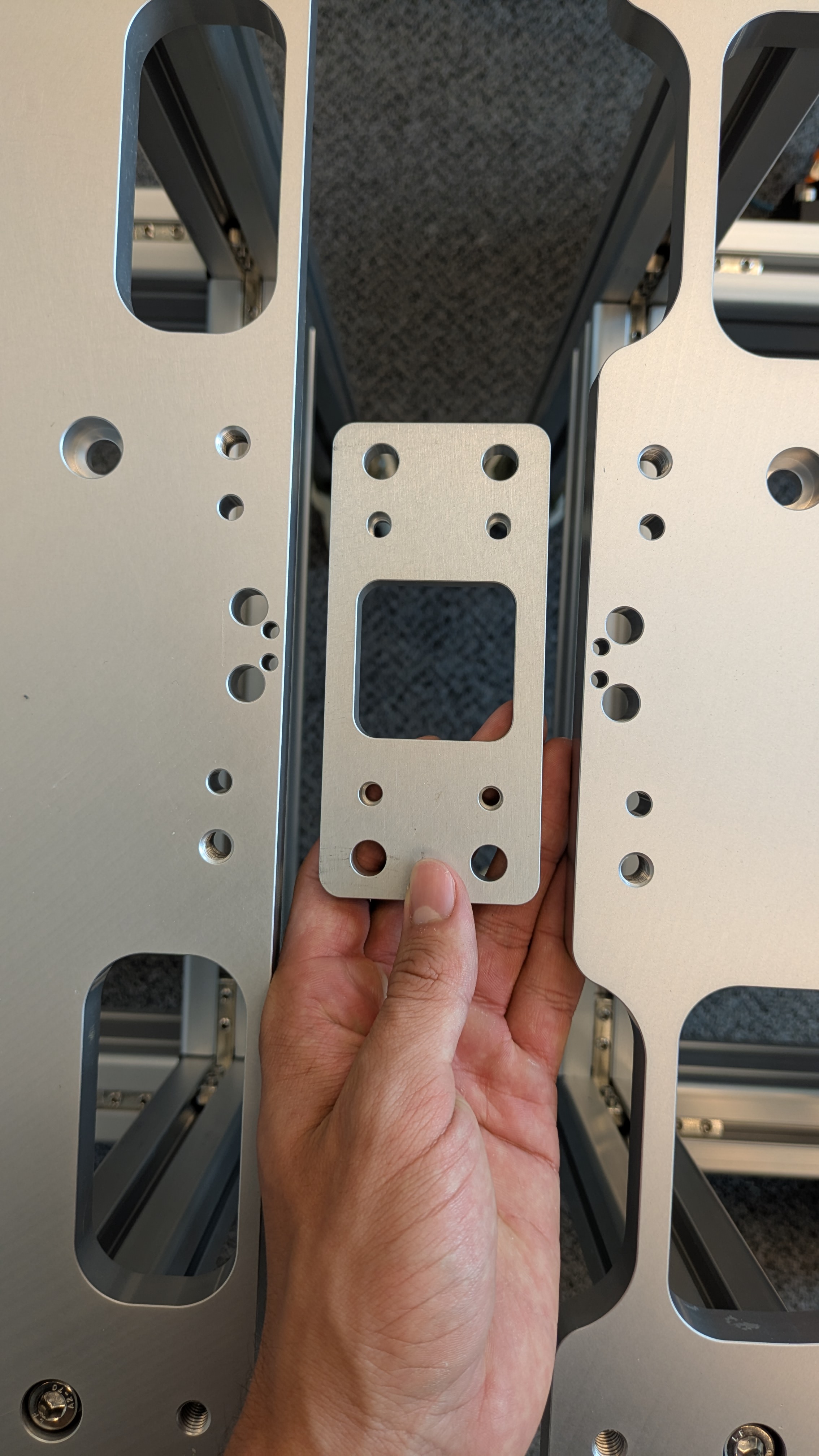
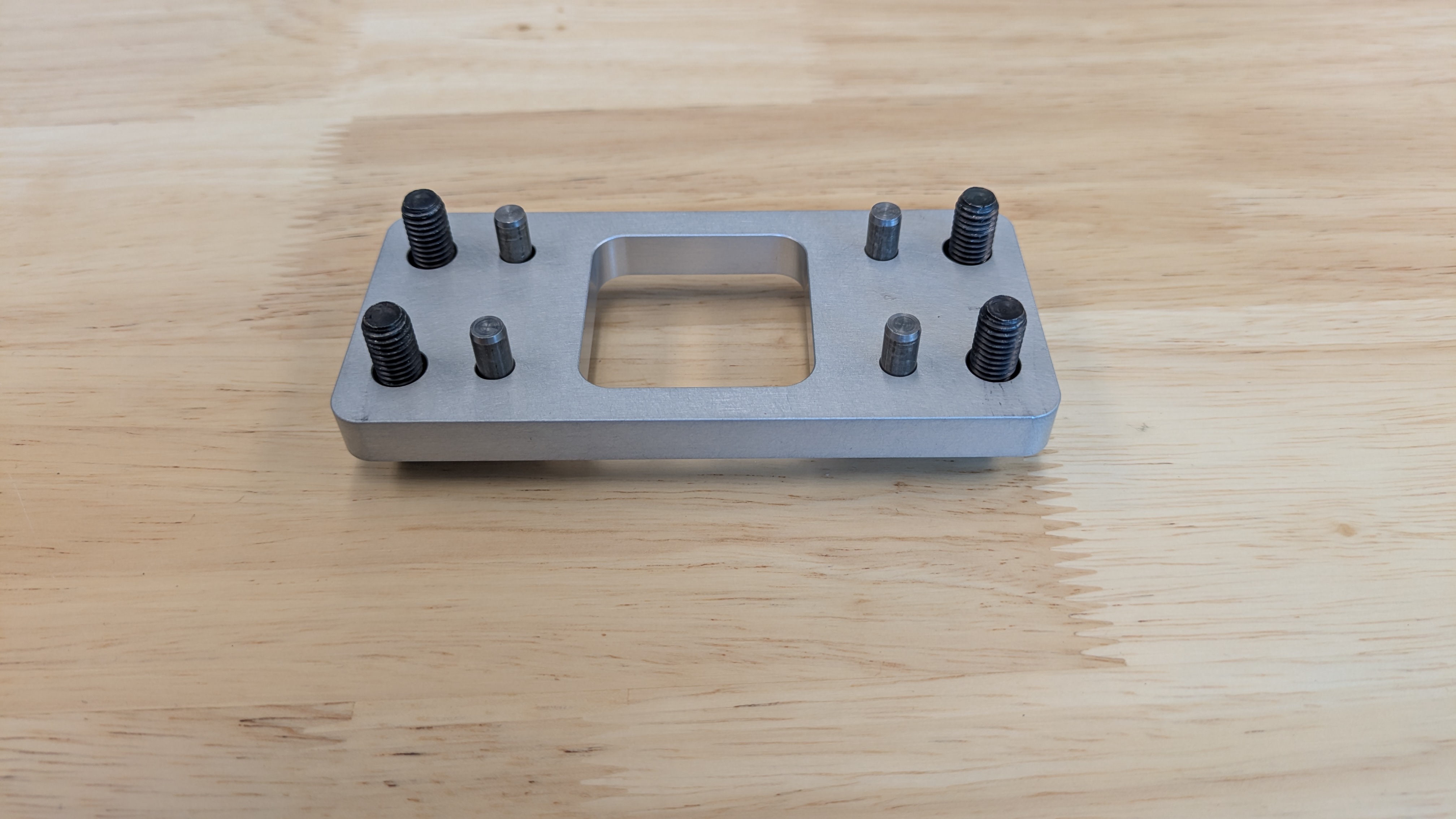
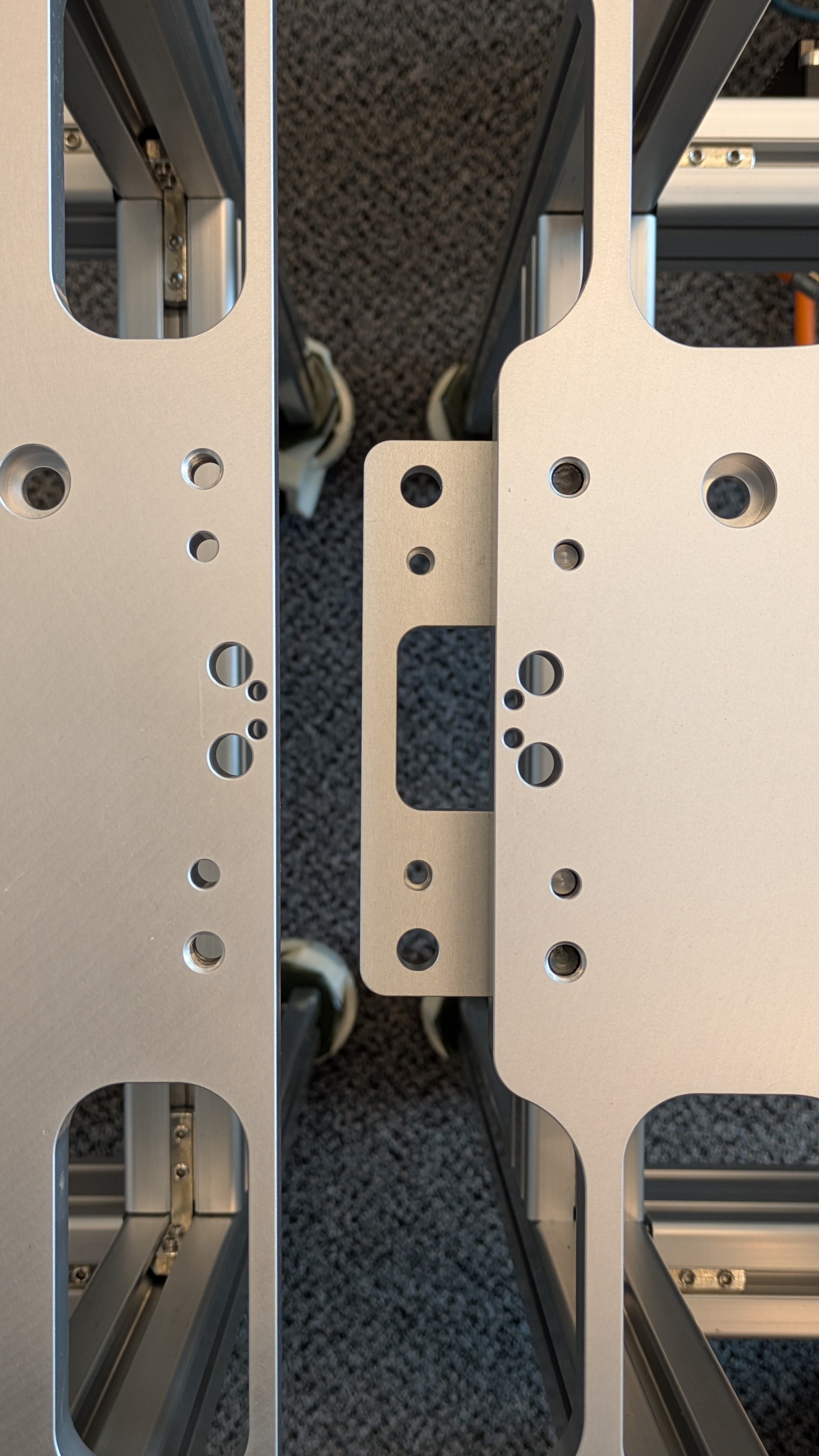
Dowel pins and coupling plates
-
The mounting plates have two dowel holes and threaded holes for screws.
-
A coupling plate has a hole and a slot for each plate that it is supposed to connect to.
-
The mounting plates are aligned, and the coupling plate is installed with dowel pins to each plate and fastened with screws.
Assembly: If using modular tables, it is recommended to arrange the empty tables in the desired layout, level them, and join them, before adding the Flyways. The tables will be much lighter and easier to work with before the Flyways are on them.
CAD Templates and Examples
The following drawings provide information on the mounting hole locations and Flyway spacing as well the shapes, sizes and locations of cutouts required on a Flyway mounting surface.
The CAD files below show example designs for modular Flyway mounting tables: