
Library Setup
Creating a new project
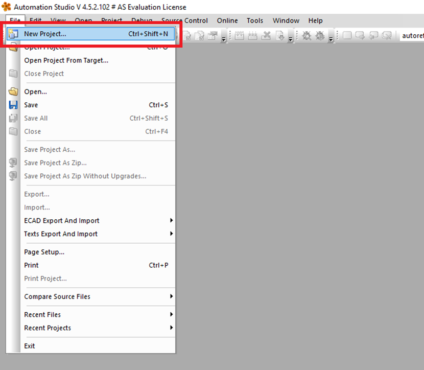
Step 1: Open Automation Studio, click File->New Project
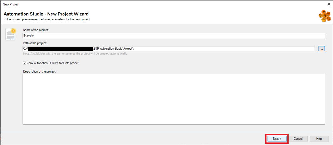
Step 2: Choose a name and location for the new project, then click "Next"
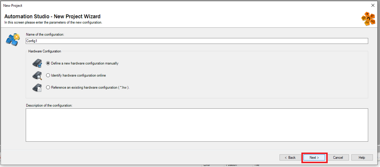
Step 3: On the next screen pick "Define a new hardware configuration manually" and click "Next"
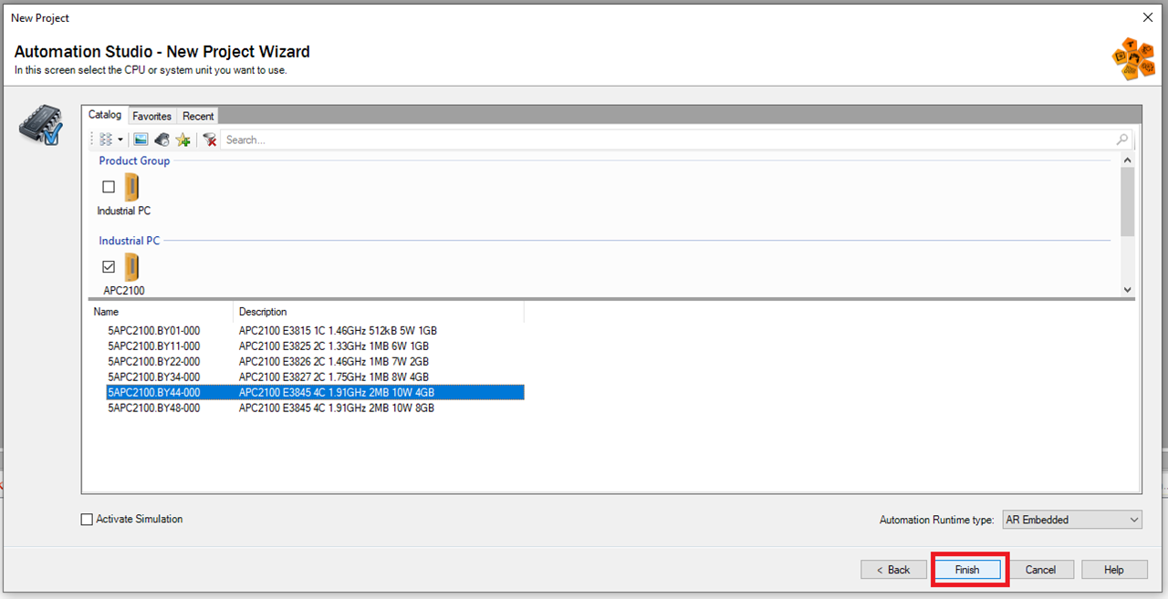
Step 4: Then choose the CPU/system unit you will be using. This example using the 5APC2100.BY44-000. Then click "Finish"
Setup Fieldbus
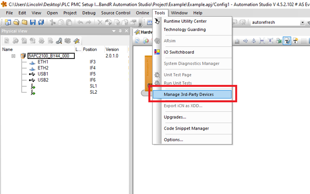
Step 1: Click Tools->Manage 3rd-Party Devices
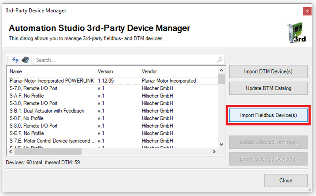
Step 2: In the 3rd-Party Device Manager window click "Import Fieldbus Device(s)"
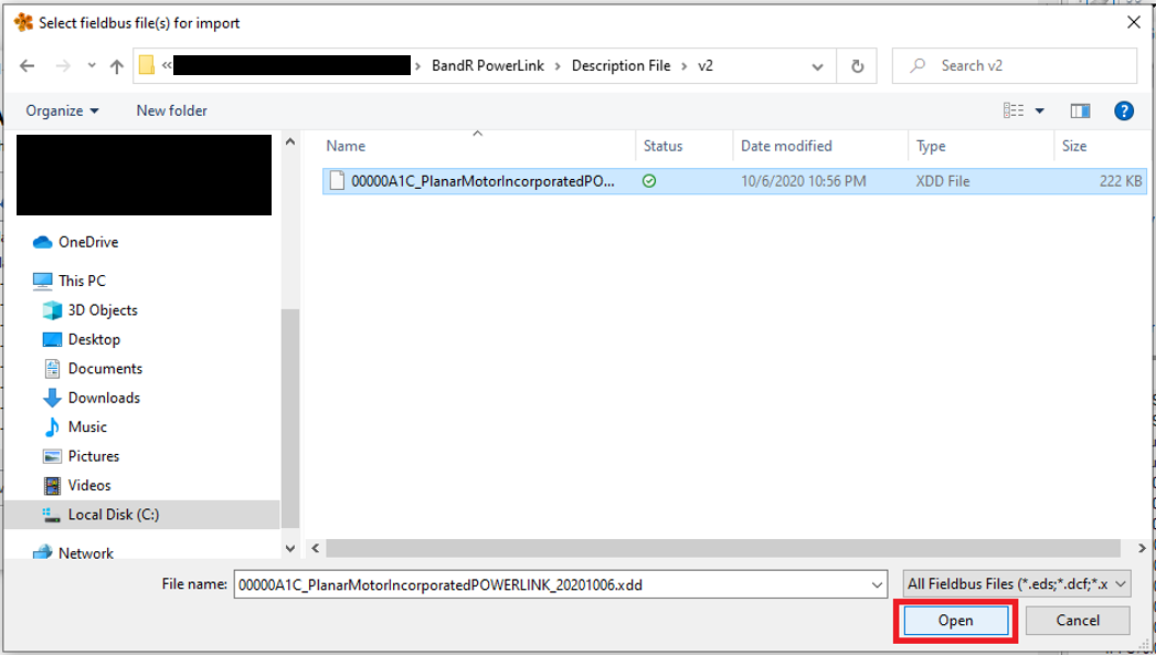
Step 3: In the Select fieldbus file(s) for import window browse to the included .xdd file and click "Open"
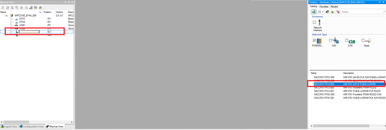
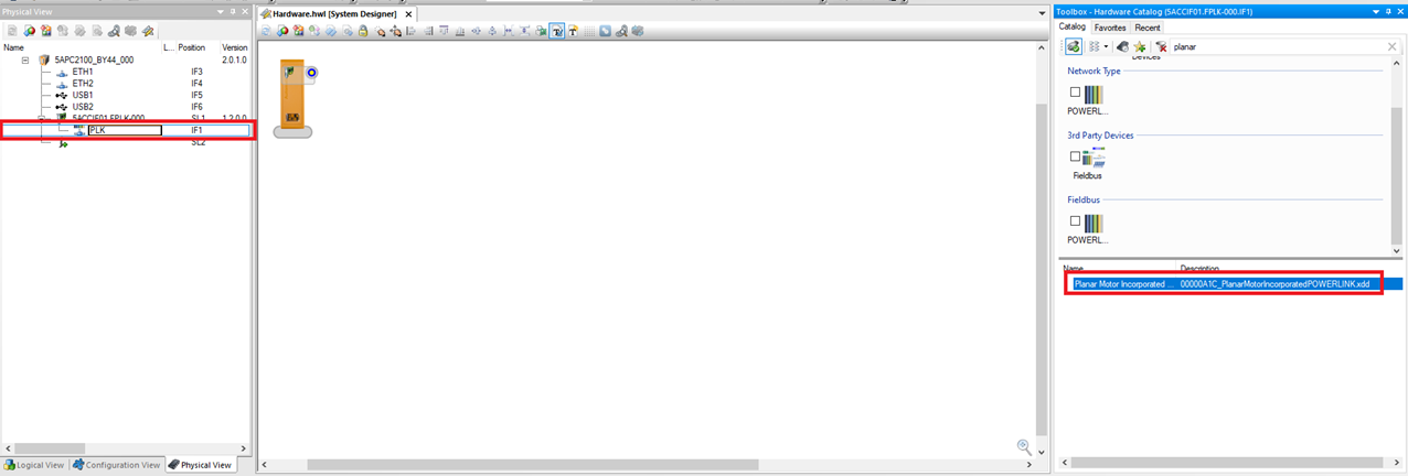
Step 4: In the Physical View select one of the empty module slots and then in the Toolbox – Hardware Catalog click the Powerlink module you are using. This example uses the "5ACCIF01-FPLK-000"
Step 5: Expand the new Powerlink module and select PLK. Then in the Toolbox search for and click the Planar Motor Incorporated Powerlink Module
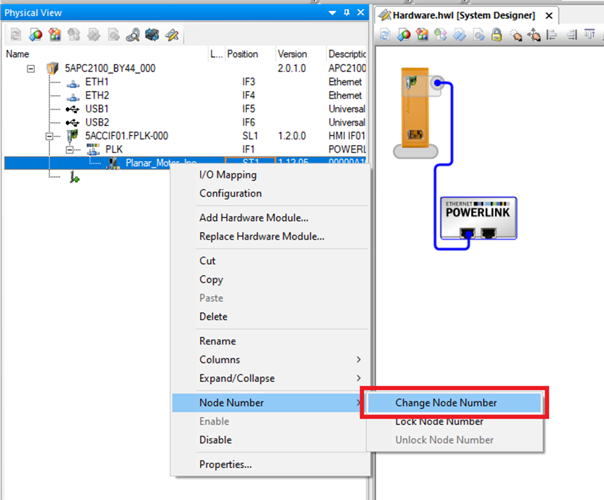
Step 6: Right click the Planar Motor Incorporated Powerlink Module and click Node Number->Change Node Number
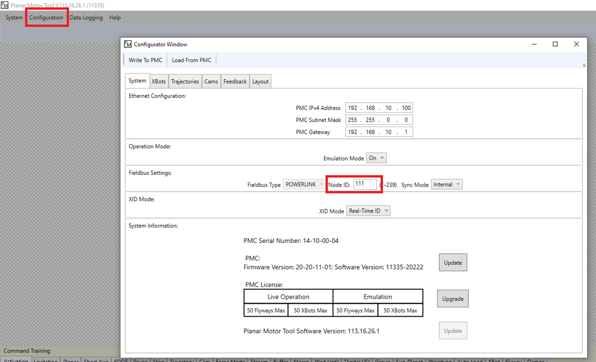
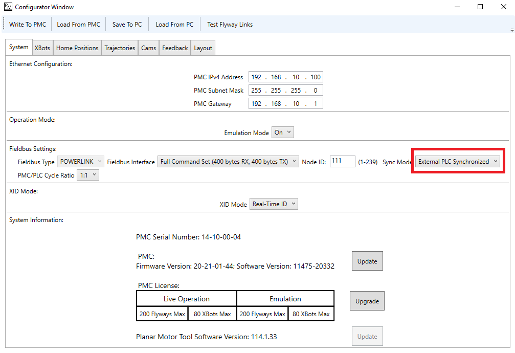
Step 7: The node number for the Planar Motor Incorporated Powerlink Module in B&R Automation Studio needs to match the Node ID in the Planar Motor Tool. You can find the Node ID in the PMT at Configuration->Open Configurator in the System Tab
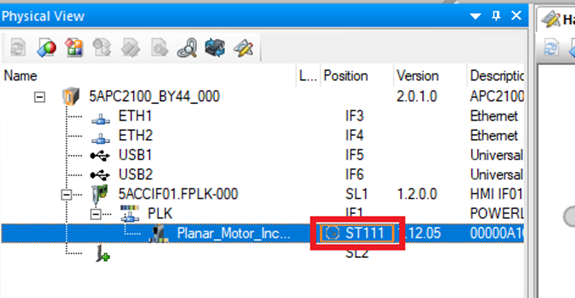
Step 8: The node number is displayed here in Automation Studio
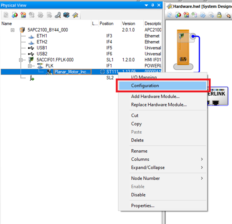
Step 9: Right click the Planar Motor Incorporated Powerlink Module and click "Configuration"
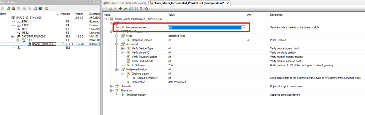
Step 10: In the Configuration window change Module supervised to off
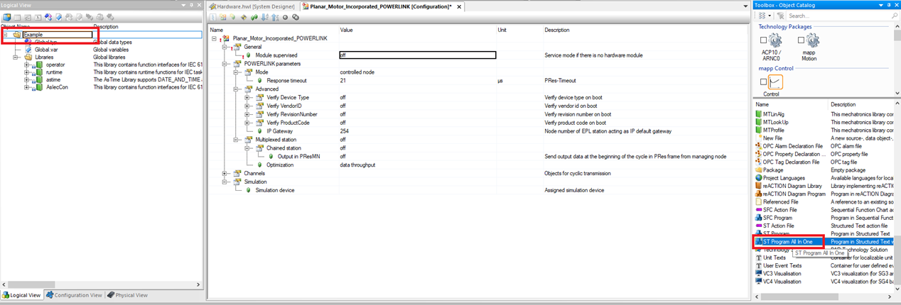
Step 11: Next select the project in the Logical View and click ST Program All In One. This adds a structured text program to the project. The library works with ladder logic too, but this example sticks to structured text.

Import and use library
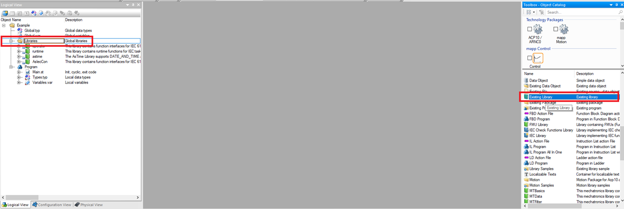
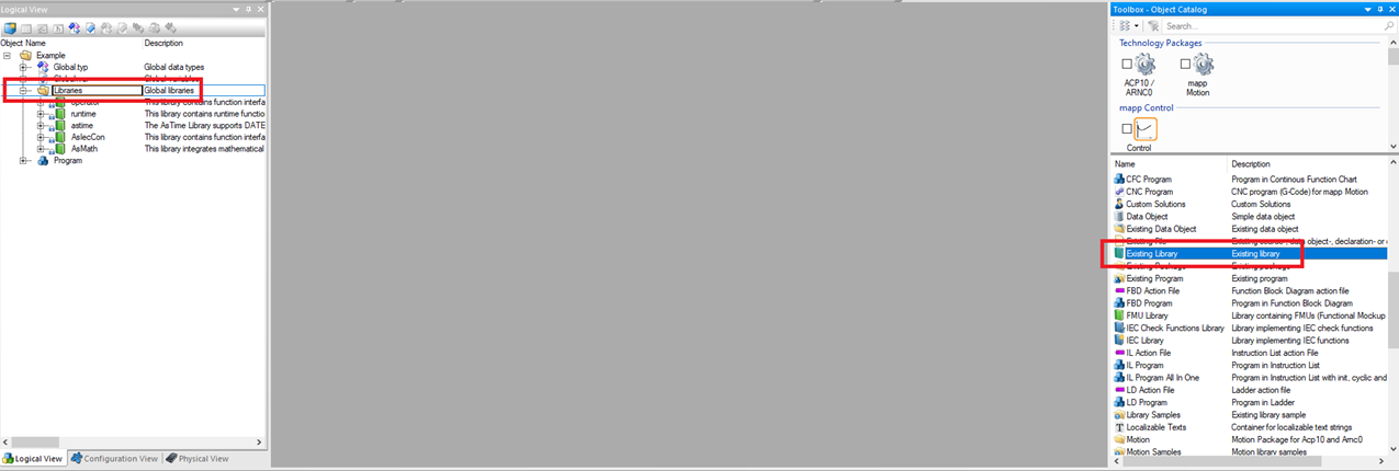
Step 1: Select Libraries in the Logical View and then click Existing Library in the Toolbox – Object Catalog
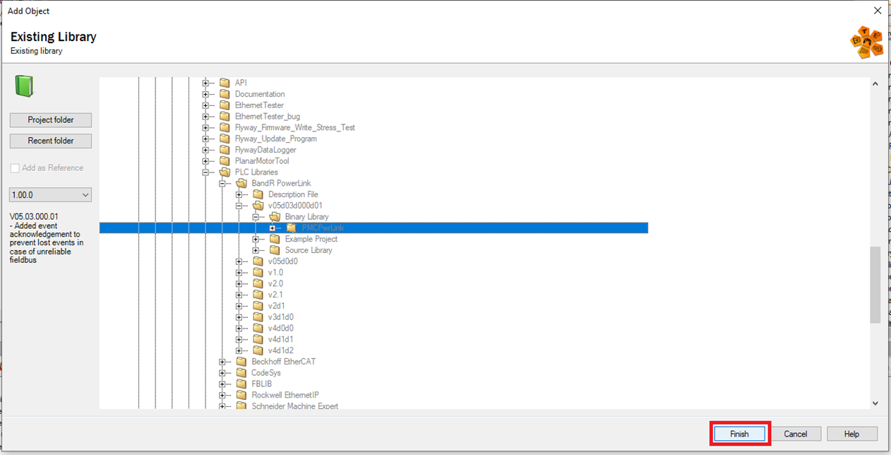
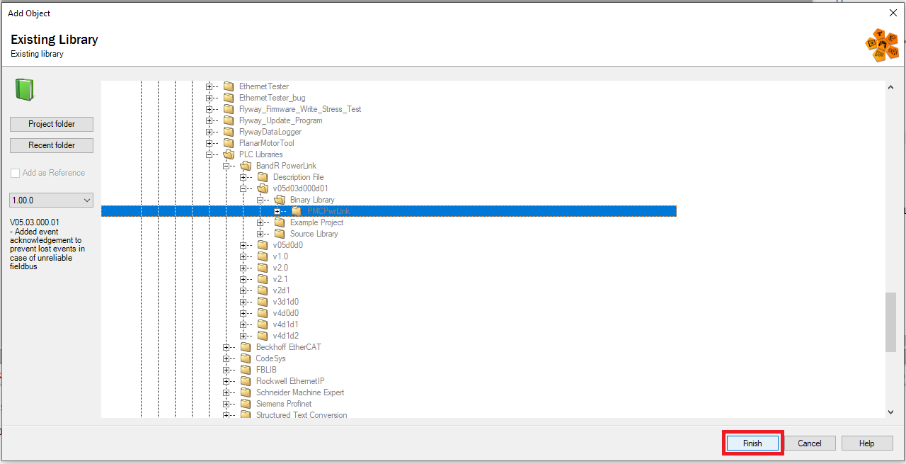
Step 2: In the Add Object window browse to the location of the PMCPwrLink library and click Finish
Step 3: Next, select the project in the Logical View and click ST Program All In One. This adds a structured text program to the project.
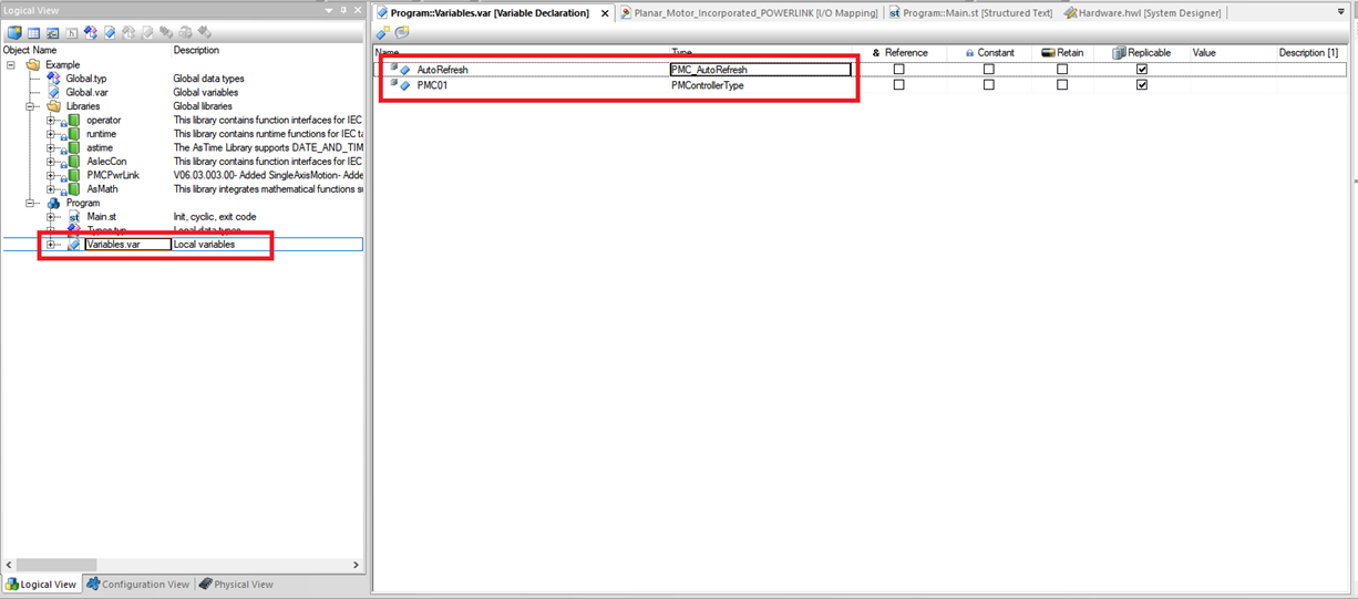
Step 4: Go into Variables.var for the new Program and declare a PMControllerType variable and a PMC_AutoRefresh function block
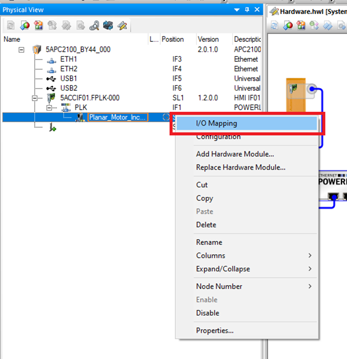
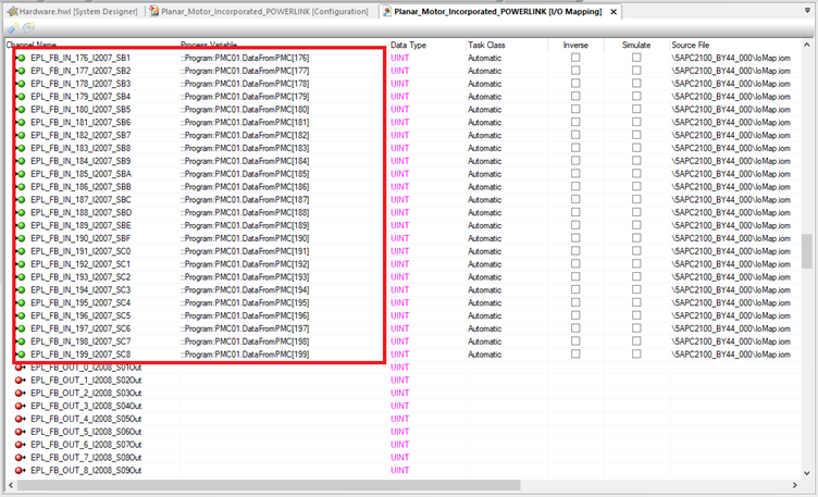
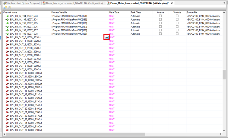
Step 5: Go to the Physical View and right click on the Planar Motor Incorporated Powerlink Module and click I/O Mapping
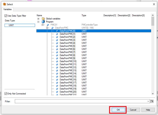
Step 6: Here you need to map each of the FB_IN elements to the corresponding element in the fieldbus in array. For the first element click the .. In the Process Variable column
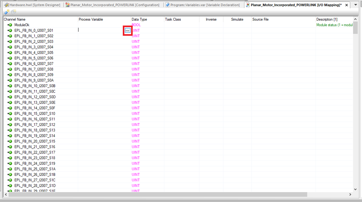
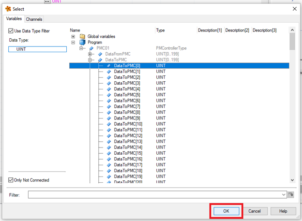
Step 7: Expand the Program then select the first element of the DataFromPMC member of the PMControllerType and click "OK“.
Step 8: For the next 199 FB_IN elements you can copy and paste the first one and just increment the index number for each one
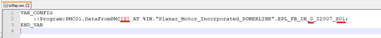
Step 8A: Alternatively, you can edit the IoMap.iom file directly. This file will be in the project directory under Physical->Config1->”Controller Name”->IoMap.iom.

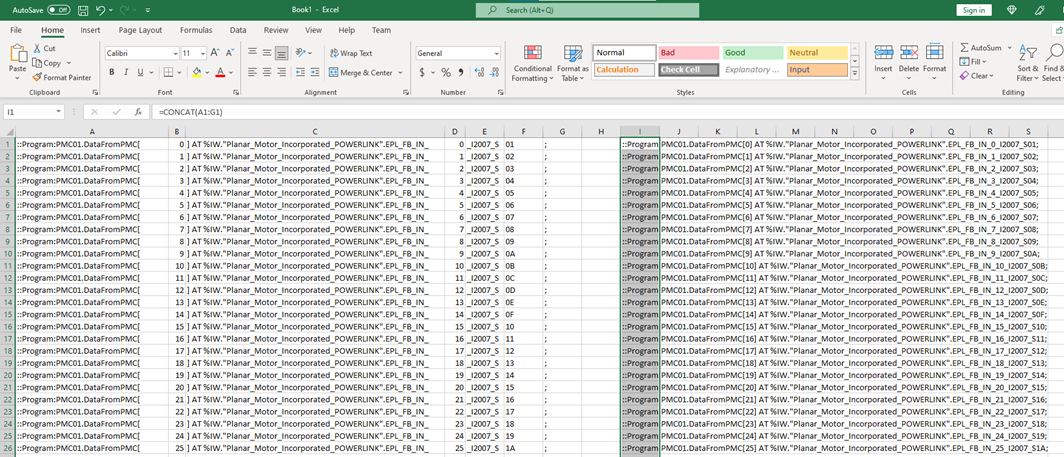
Step 8B: Opening the IoMap.iom file shows that it is a simple plaintext file. The mappings are stored as lines of text with a simple pattern. The three underlined numbers increment for each line and the rest stays the same. A spreadsheet program (Excel, Google Sheets, LibreOffice Calc, etc.) can be used to auto generate these lines of text and copy and paste them into the IoMap.iom file.
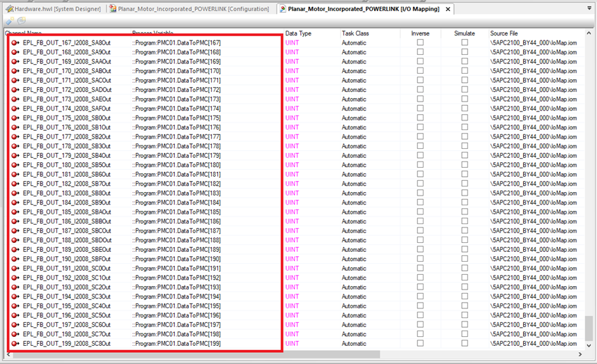
Step 9: Then you need to do the same for the FB_OUT elements. These elements will be mapped to the corresponding elements in the fieldbus out array. For the first element click the .. In the Process Variable column
Step 10: Expand the Program then select the first element in the fieldbus out array and click "OK"
Step 11: For the next 199 DataToPMC elements you can copy and paste the first one and just increment the index number for each one
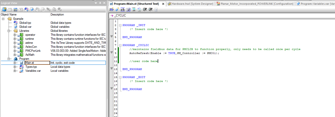
Step 12: In Main.st make sure the following is done;
-
For user code, all PMC function blocks have a PM_Controller in/out variable. Use the one declared earlier as a global variable (in step 4)
-
Make sure that one and only one instance of the PMC_AutoRefresh function block is declared and that the PMC_AutoRefresh function block is called once and only once per PLC cycle
Upgrade Library
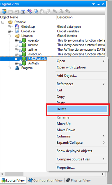
Step 1: First go into the Logical View and right click the old library and click "Delete"
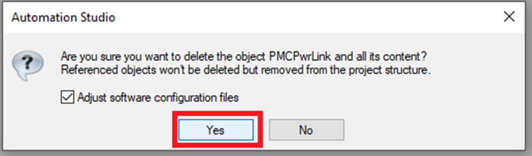
Step 2: Click "Yes" on the confirmation window
Step 3: Then select Libraries in the Logical View and click Existing Library in the Toolbox
Step 4: In the Add Object window browse to the location of the new library and click "Finish"
Setup Streaming (Optional) - only for synchronization with external axis
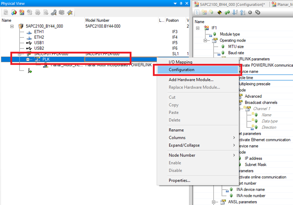
Step 1: In the Physical View expand the Powerlink module that the PMC is connected to and right click "PLK". Then click "Configuration".
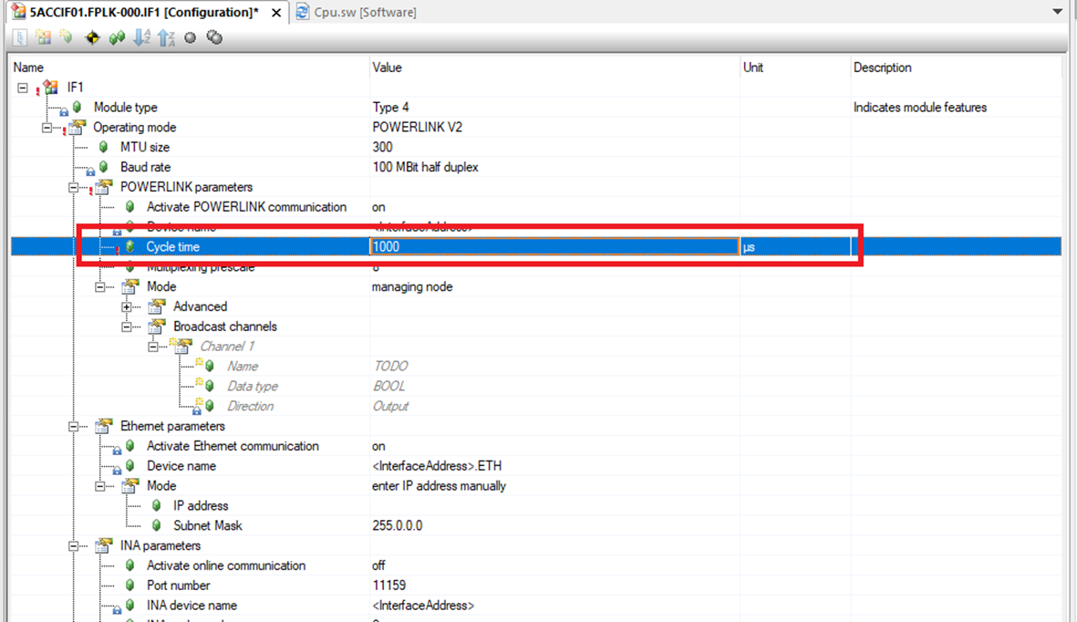
Step 2: In the Configuration window for the module PLK go to Operating mode->POWERLINK parameters and make sure that the Cycle time is the same as the cycle time of the task that communicates with the PMC.
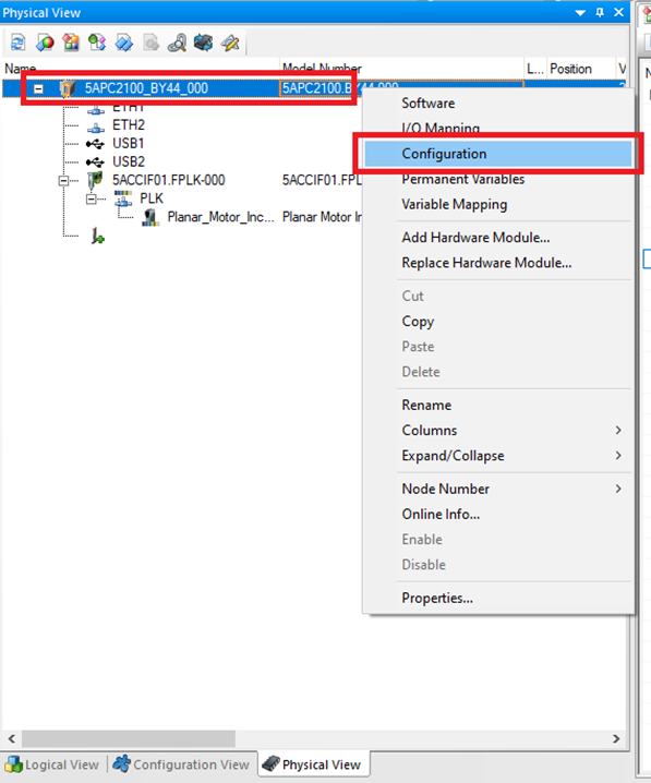
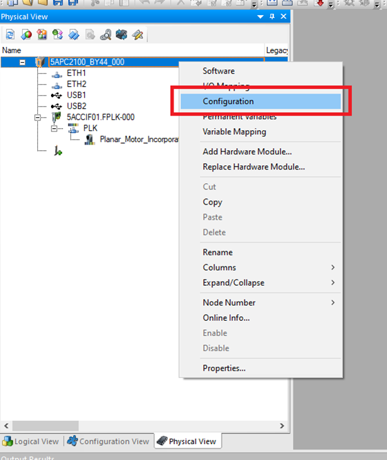
Step 3: In the Physical View right click the CPU and select "Configuration".
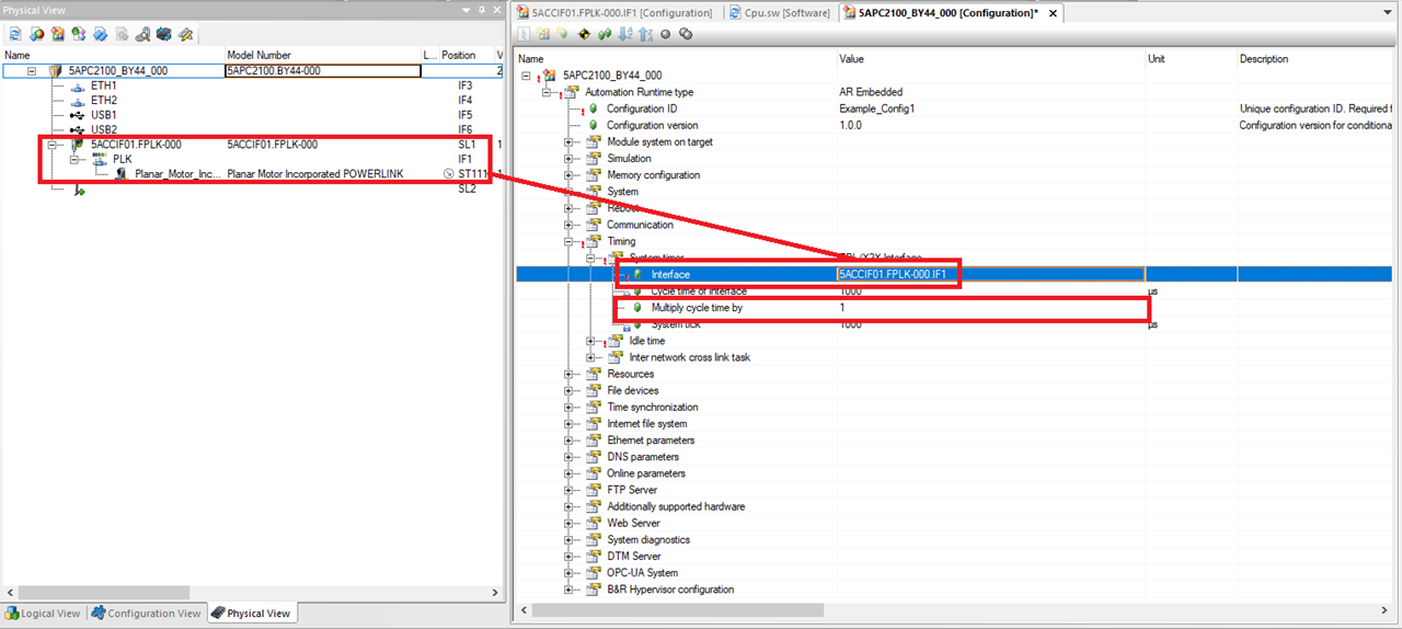
Step 4: In the Configuration window for the CPU go to Automation Runtime type->Timing->System timer and change the System timer to EPL/X2X Interface.
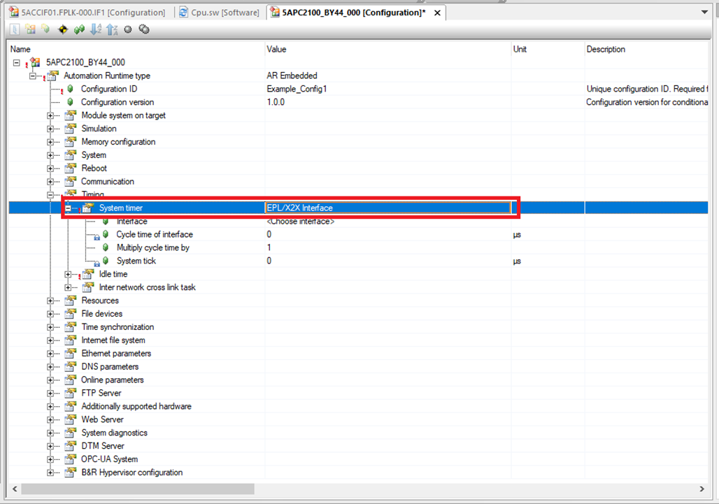
Step 5: Then make sure that the Interface is the same one that is connected to the PMC and that Multiply cycle time by is set to 1.
Step 6: In the Planar Motor Tool, open the Configurator, then select “External PLC Synchronized” for the Sync Mode.
Step 7: Click "Write To PMC" to save the configuration to the PMC.
File I/O on the PLC (Optional)
The following are one possible way to read and write files to the PLC storage. It could be helpful for commands such as Set PMC Configuration.
Step 1: We can access files on the B&R PLC using the FTP server. In the Physical View right click the PLC and select Configuration
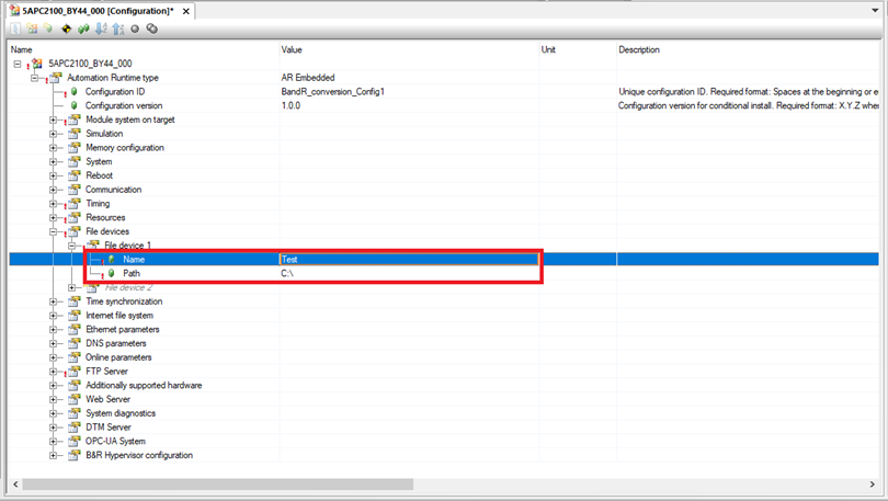
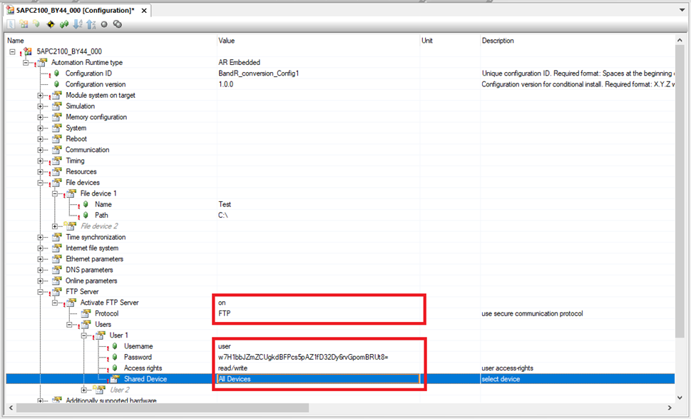
Step 2: In the Configuration window go to PLC->Automation Runtime type->File devices. Create a File device by specifying a name and drive number.
Step 3: Next go to PLC->Automation Runtime type->FTP Server. Switch Activate FTP Server to “on” and select FTP for the Protocol. Then setup a user with read/write Access rights and All Devices for the Shared Device.
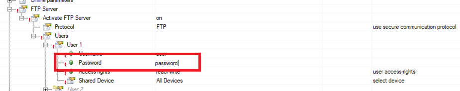
Step 4: Note that B&R Automation Studio will encrypt the typed Password for the User. For example, “password” is used here for the Password.
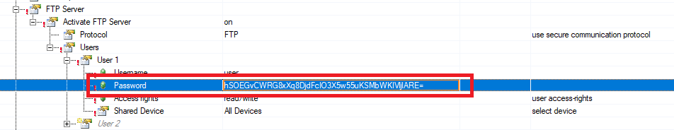
Step 5: And as soon as enter is pressed, it turns into random characters. The Password is still “password”, but it is hidden in Automation Studio.
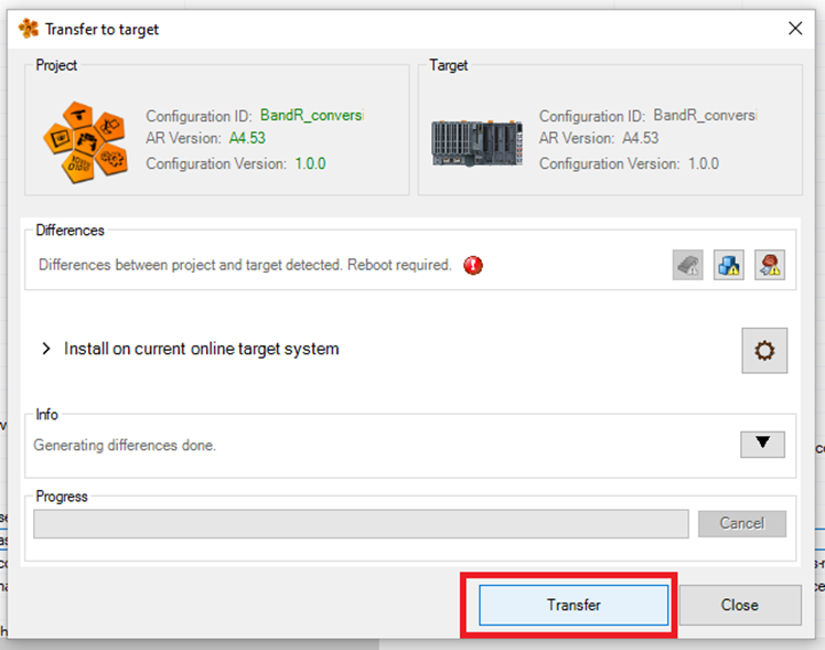
Step 6: Once the File device and FTP server is configured, build the project, and Transfer it to the PLC.
Step 7: Once the PLC reboots, you will need to open a program that can access FTP servers. This example will use WinSCP.
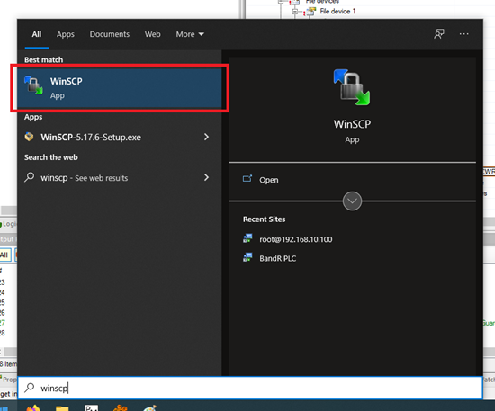
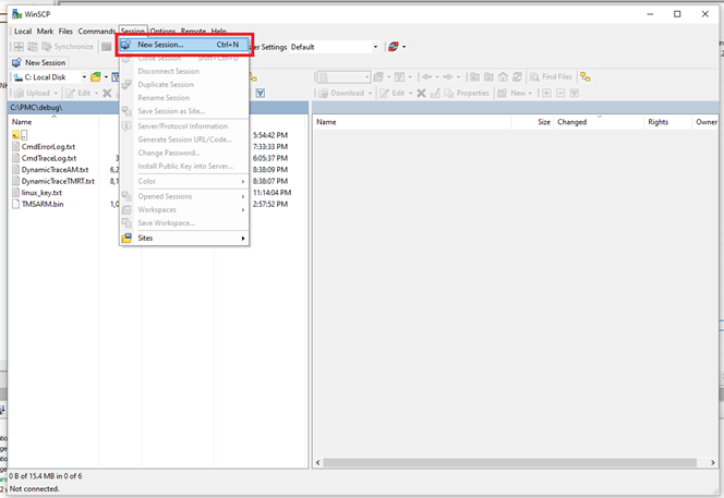
Step 8: In WinSCP click Session->New Session…
Step 9: In the Login window choose New Site. Choose FTP for the File protocol. The Host name is the IP address of the PLC. Use the Username and Password configured earlier. Then click Login.
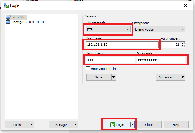
Step 10: You can now access the files on the PLC.