
This guide is for the wiring setup of the PMC and Flyways.
Maintenance work on a Planar Motor System that is still connected to the power source may result in injury or death. Before performing any work on the Planar Motor System, they must first be disconnected from the power system and prevented from being switched on again. Only qualified electrical personnel are permitted to carry out maintenance work on a Planar Motor System.
Planar Motor Network (PMNet) Wiring
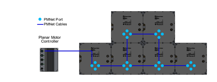
One data cable is installed between every two adjacent Flyways, using the two closest ports as shown. The Planar Motor Controller (PMC) can be connected to any of the PMNet ports.
Make sure the PMNet cables are fully inserted, and the rotating collar locks onto the cable properly.
Flyway Power and PMC Power Cable Wiring
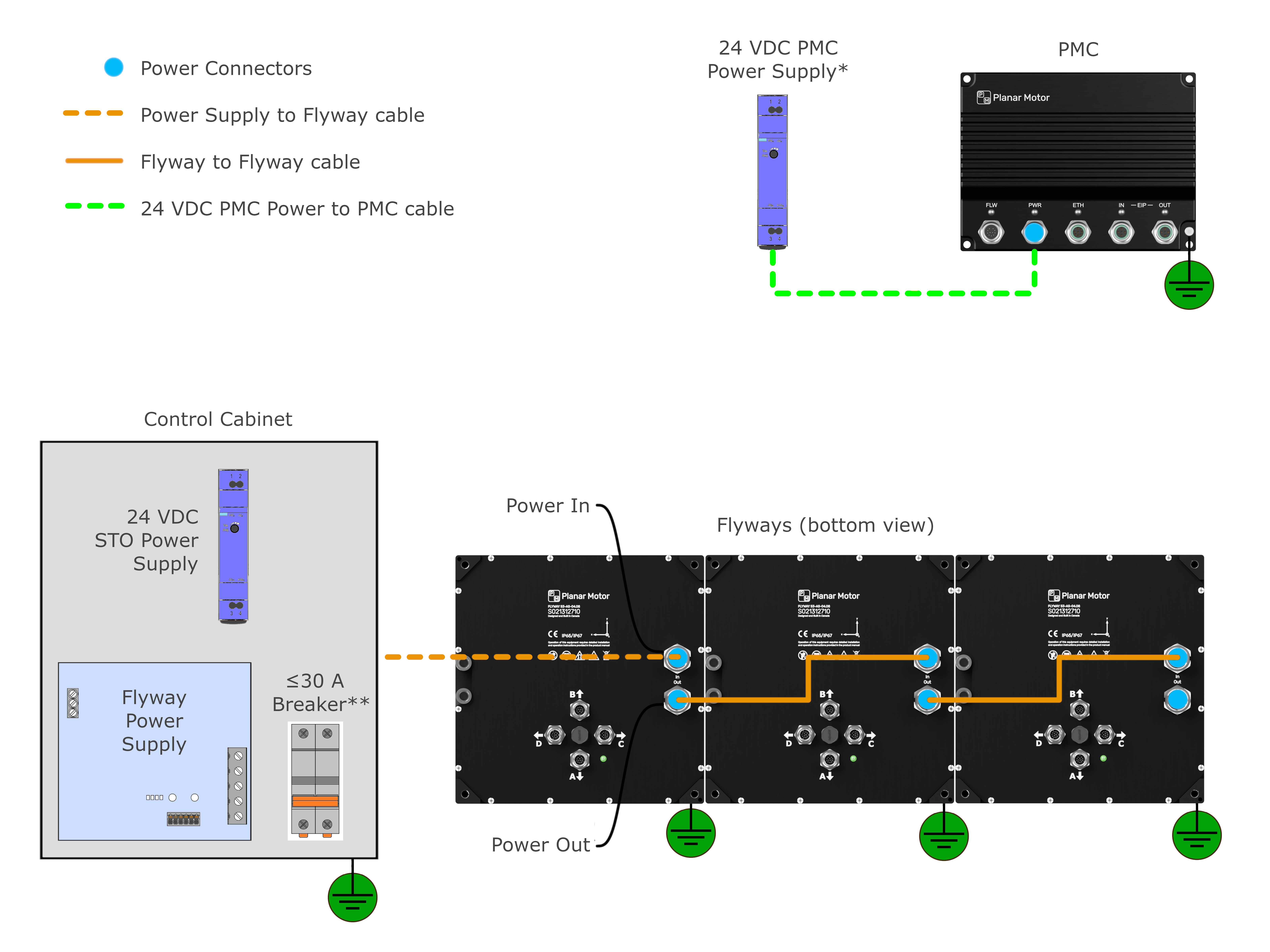
* The nominal power supply voltage for the PMC is 24 VDC. The PMC is capable of operating from a power supply voltage between 18-58 VDC.
** Breaker is not required if using PS-1500-DIN or PS-1500-XX-YY-Z
|
Flyway Series |
Nominal Flyway Power Supply Voltage |
|---|---|
|
S3 |
48 VDC |
|
S4 |
54 VDC |
Flyway power cables can be daisy-chained as shown above. In most applications, a 1kW power supply can power up to eight 3-Series (or five 4-Series) Flyways and eight XBots. Contact the manufacturer for assistance in determining your power supply requirements.
.png)
.png)
Each power cable has a female end (to be connected to PWR IN on the Flyway) and a male end (to be connected to PWR OUT on the Flyway).
The Flyway power connector is equipped with a rotating spring latch. Make sure the latch is fully rotated after installing the cable to ensure the cable is properly secured to the Flyway.

Damage can occur due to improper wiring. Power connectors are only permitted to be connected in a voltage-free state. Wiring under voltage will irreparably damage connected devices.
Grounding Requirement
-
Each Flyway and the PMC should be grounded.
-
For the Flyways, any of the four threaded mounting holes can be used as a ground connection point.
-
For the PMC, a separate grounding hole is provided on the aluminum body of the PMC
-
-
An adequate ground path should be provided for each piece of hardware, such as using a grounded mounting plate to mount the Flyways at the site.
Control Cabinet Flyway Power Wiring
A Planar Motor System can be provided with the power supply wired and enclosed.
When wiring the power supply cables to the power supply unit, the following instructions should be followed.
See instructions

|
Function |
Cable Wire Colour |
Cable Cross-Section Area |
Connection |
|---|---|---|---|
|
Power Supply. 48/54 VDC relative to Power Supply Return |
Red |
AWG 10, 6mm2 |
48/54 VDC on the power supply unit |
|
Power Supply Return |
Black |
AWG 10, 6mm2 |
48/54 VDC Return on the power supply unit |
|
STO+ |
White |
AWG 22, 0.34mm2 |
STO device high side |
|
STO- |
Green |
AWG 22, 0.34mm2 |
STO device low side |
|
Field Earth (FE) |
Green |
AWG 14, 2.5mm2 |
Field Earth |
Wiring Steps:
-
Connect the red wire to 48/54 VDC
-
Connect the black wire to 48/54 VDC Return
-
Connect the white wire to high side of STO device
-
Connect the green wire (AWG 22) to low side of STO device
-
Connect the green wire (AWG 14) to the field earth
-
Connect 48/54 VDC Return to the field earth
Control Cabinet PMC Power Wiring
The PMC is typically powered in one of the following two ways:
-
24 VDC Power Supply
-
48/54 VDC Flyway Power Supply
The PMC power cables also contain a single digital input and a single digital output channel, which can be wired to an auxiliary digital I/O device. The digital I/O capabilities of the PMC can be used to trigger actions to and from the Planar Motor System. For more information on implementing the digital I/O capabilities of the PMC, please contact the manufacturer.
For customers wiring the PMC power cable to a power supply unit, the following instructions should be used.
See instructions

|
Function |
Cable Wire Colour |
Cable Cross-Section Area |
Connection |
|---|---|---|---|
|
Power Supply. 48/54 VDC relative to Power Supply Return |
Brown |
AWG 22, 0.34mm2 |
48/54 VDC on the power supply unit |
|
Power Supply Return |
White |
AWG 22, 0.34mm2 |
48/54 VDC Return on the power supply unit |
|
Digital Input to PMC |
Black |
AWG 22, 0.34mm2 |
Output of Digital I/O Device or Field Earth |
|
Digital Output from PMC |
Blue |
AWG 22, 0.34mm2 |
Input of Digital I/O Device or leave unconnected |
|
Field Earth (FE) |
Grey |
AWG 22, 0.34mm2 |
Field Earth |
Wiring Steps:
-
Connect the brown wire to 48/54 VDC
-
Connect the white wire to 48/54 VDC Return
-
If using, connect the blue wire to input of external Digital I/O device, this will be connected to the digital output signal of the PMC. Otherwise protect wire conductor with heat shrink and leave unconnected.
-
If using, connect the black wire to output of external Digital I/O device, this will be connected to the digital input signal of the PMC. Otherwise connect to 48/54 VDC Return.
-
Connect the grey wire to the field earth
-
Connect 48/54 VDC Return to the field earth
STO Wiring
All safety circuits should be designed and implemented according to the relevant SIL / PL standards. This document provides instruction on how to integrate the STO signal into the safety circuit, but does not determine auxiliary safety devices.
The STO+ signal can be connected to safety switches or digital outputs to enable or disable the Flyway motor power under specific circumstances. If the STO+ signal is set to low, the power stage is disabled. For instance, a positively driven switching off relay can be used disable the motor power when the safety circuit is opened.
