
This guide is for the installation of liquid cooling for the Flyways. For more technical details regarding liquid cooling, refer to Liquid Cooling Guide.
Ports and Tubing
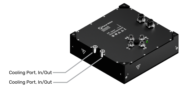
Active cooling is not required to operate the Planar Motor System, but can be used in temperature sensitive applications. Each Flyway has cooling channels integrated into the aluminum body of the hardware.
Input/output push-to-connect cooling ports located under the Flyway provide options for water cooling. The ports are non-polar. You may connect the coolant line to either port as the inlet; the other port will then act as the outlet.
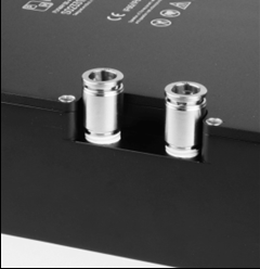
Fittings mate to the Flyway with pipe threads, and can be removed using their internal hex drive if desired. Note the following specifications of Flyway cooling port fittings:
-
Thread: 1/4” NPT
-
Drive size: 6 mm internal hex drive
-
Fitting torque: Fittings must be torqued to 10 Nm
When selecting liquid cooling tubing, the following recommendations apply:
-
Semi-flexible, to bend around flyway mounting supports, cables, or other obstacles
-
Durometer (hardness) of 95A
-
Compatible with push-to-connect style fittings
Some examples of recommended tubing
Coolant Circuit Configuration
Flyway coolant ports are non-polar; any port on any Flyway can be used for coolant input. Typical coolant circuits (series and parallel) may look like the following:
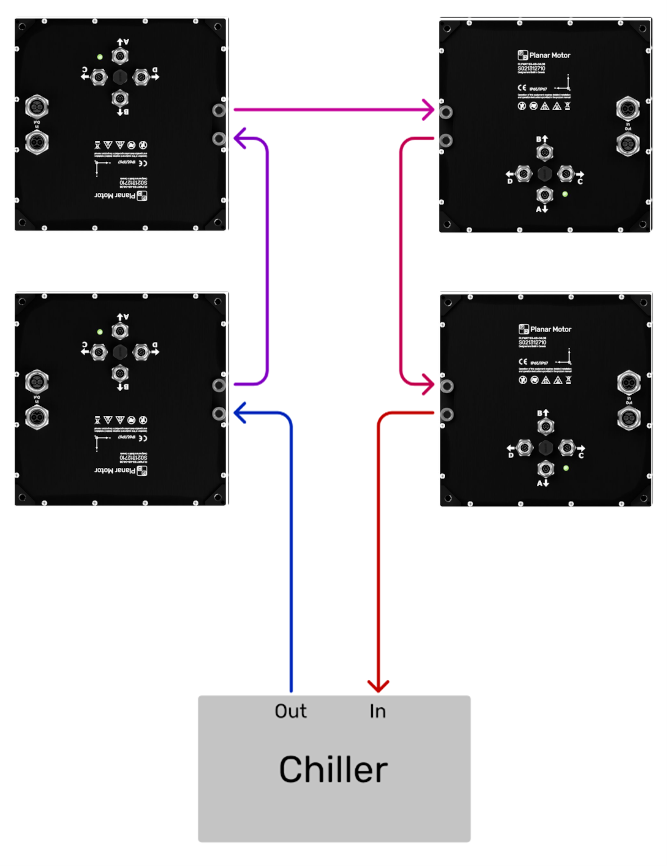
Parallel configurations are recommended whenever possible.
It is not recommended to configure more than 8 Flyways in series.
Exceeding 8 Flyways may require a coolant pressure differential greater than the maximum rated pressure of the Flyway cooling system. Additionally, there may be an excessive temperature gradient along a series chain, such that Flyways near the end of a chain may not perform suitably for demanding applications.
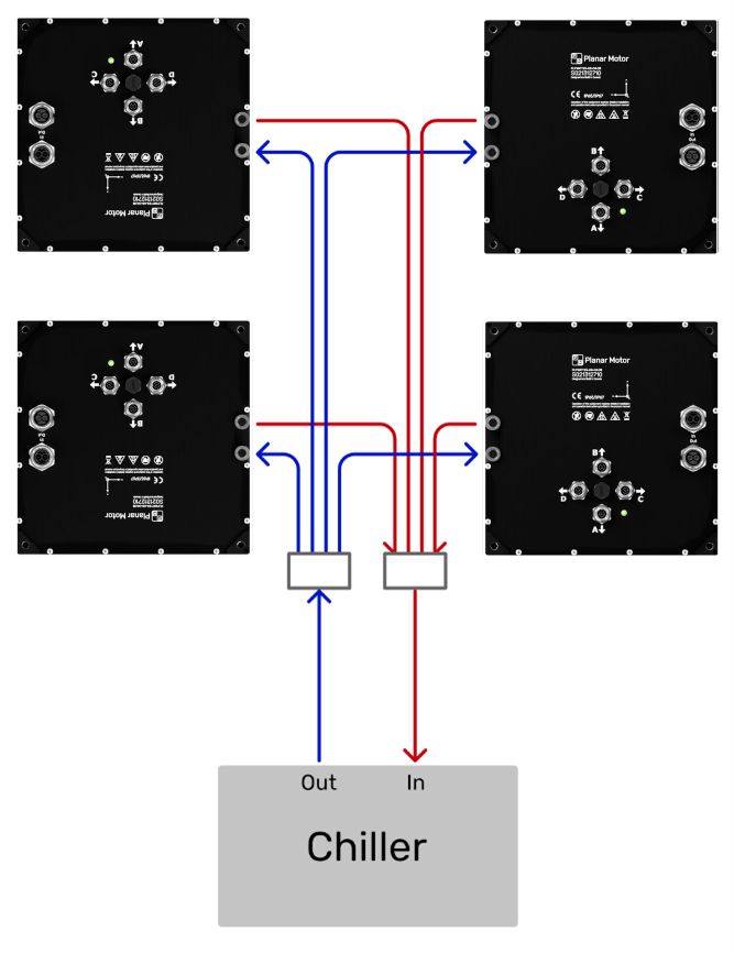
In practice, strictly parallel configurations are not always possible. It is common for integrators to use series-parallel combination circuits to achieve the desired cooling performance. A typical series-parallel combination circuit may look like the following:
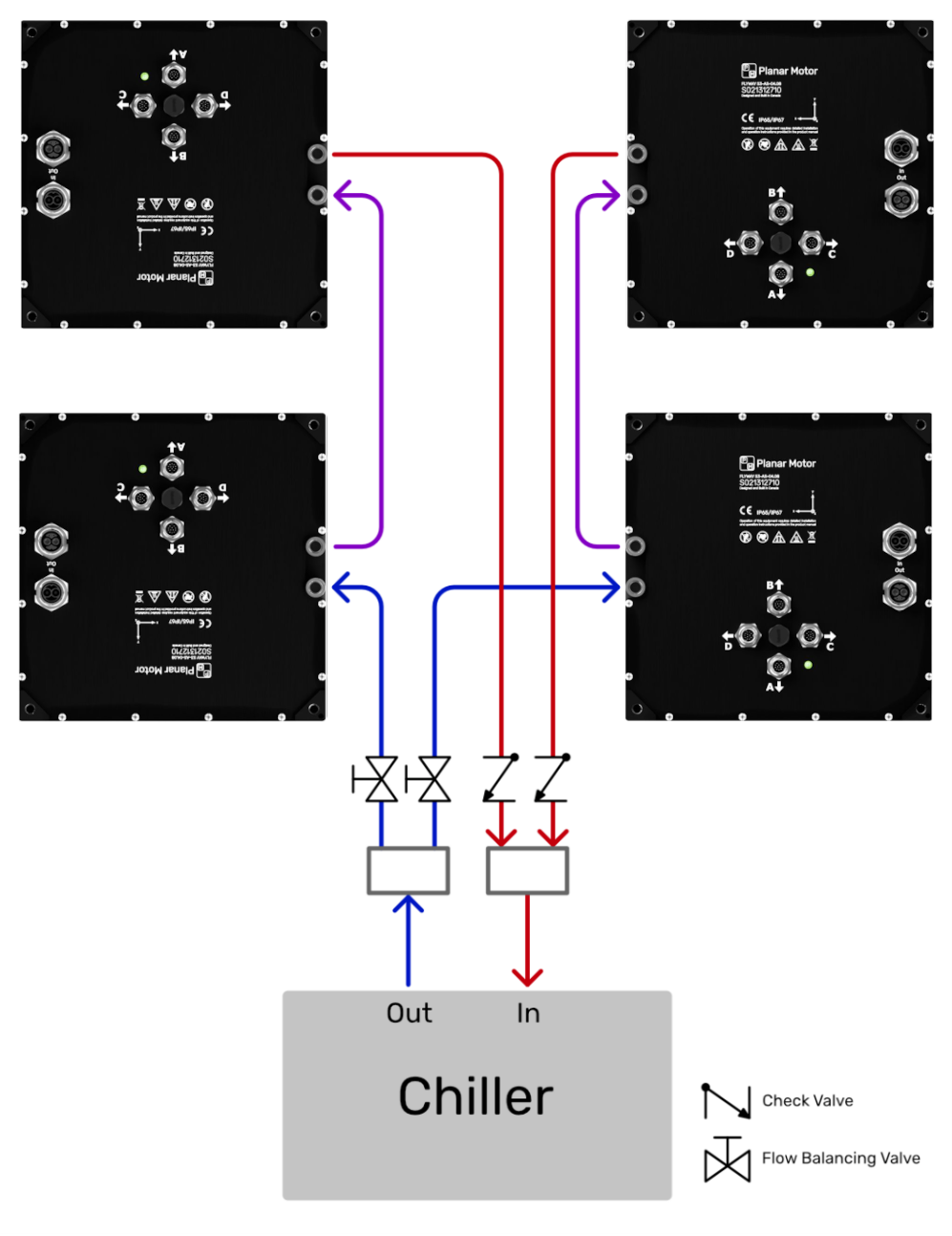
When connecting the Flyways in parallel, system integrators should consider adding flow balancing valves to each branch, and check valves at the output of each Flyway branch.
Most chillers have an open tank; there is no requirement to bleed air from the system – it will be expelled from the system as the chiller pump moves coolant through the coolant channels. Contact Planar Motor support if a hydraulically-closed coolant solution is required.