Library Setup
Creating a new project
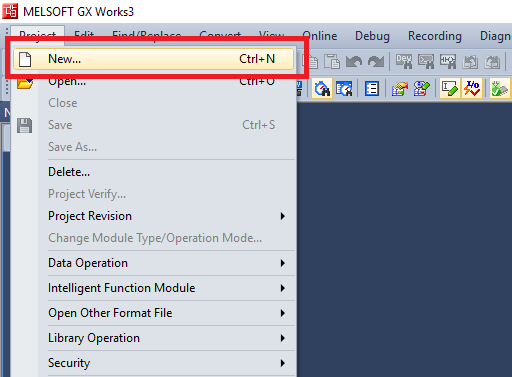
Step 1: Click on Project->New
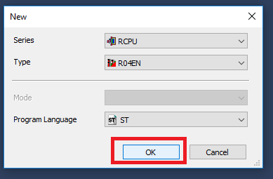
Step 2: In the New Project window select the Controller Series, Controller Type, and Program Language. Then click "OK"
The library is fully compatible with ladder diagram. We will be using Structured Text for consistency with the included example project.
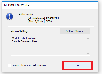
Step 3: Click "OK" in the Add Module dialogue window
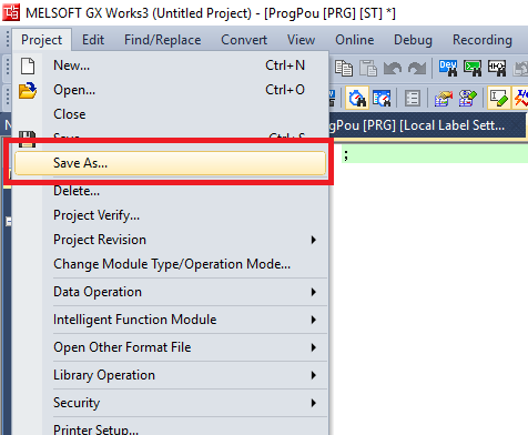
Step 4: To name the project, you will have to save the project. Click Project -> Save As
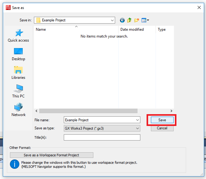
Step 5: Navigate to the directory where you want to store the project. Give the project a file name then click Save
Setup Fieldbus
Steps 1-3 are only needed if this GX Works 3 installation hasn’t used the PMC CC-Link module
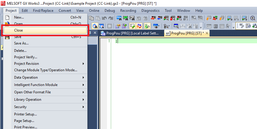
Step 1: If you currently have a project open close it. You can only register a CC-Link device if no project is open
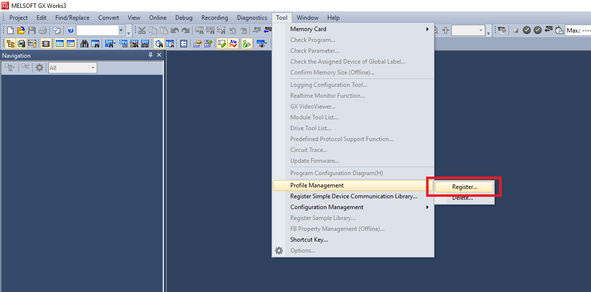
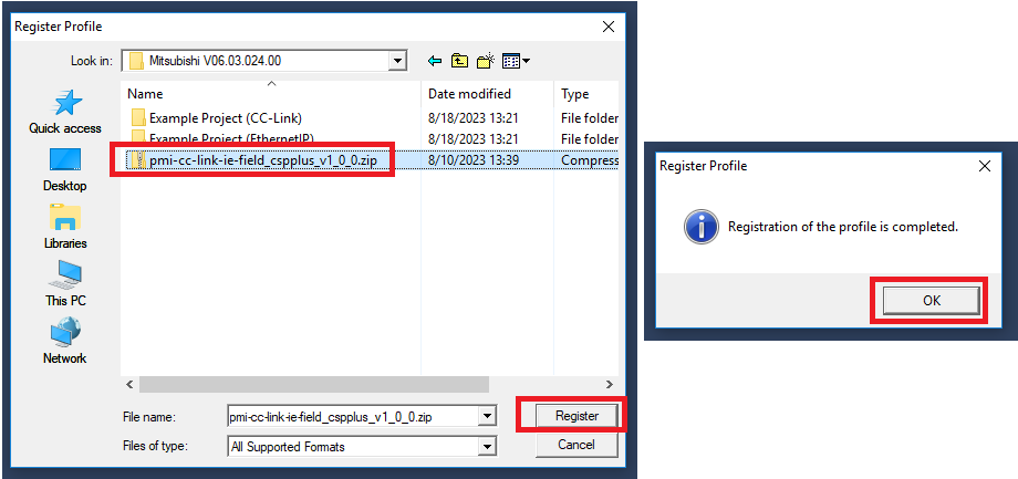
Step 2: Click Tool->Profile Management -> Register
Step 3: Navigate to the PMC CC Link zip file, select it and then click Register. Click OK in the confirmation window
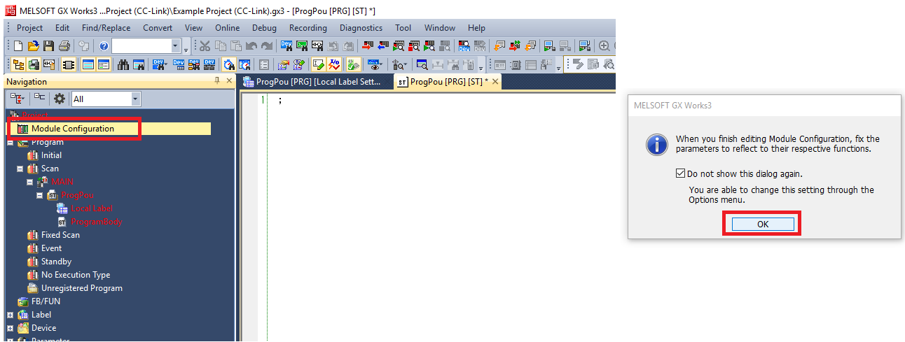
Step 4: Double click on Module Configuration in the Navigation window. Click OK in the pop-up
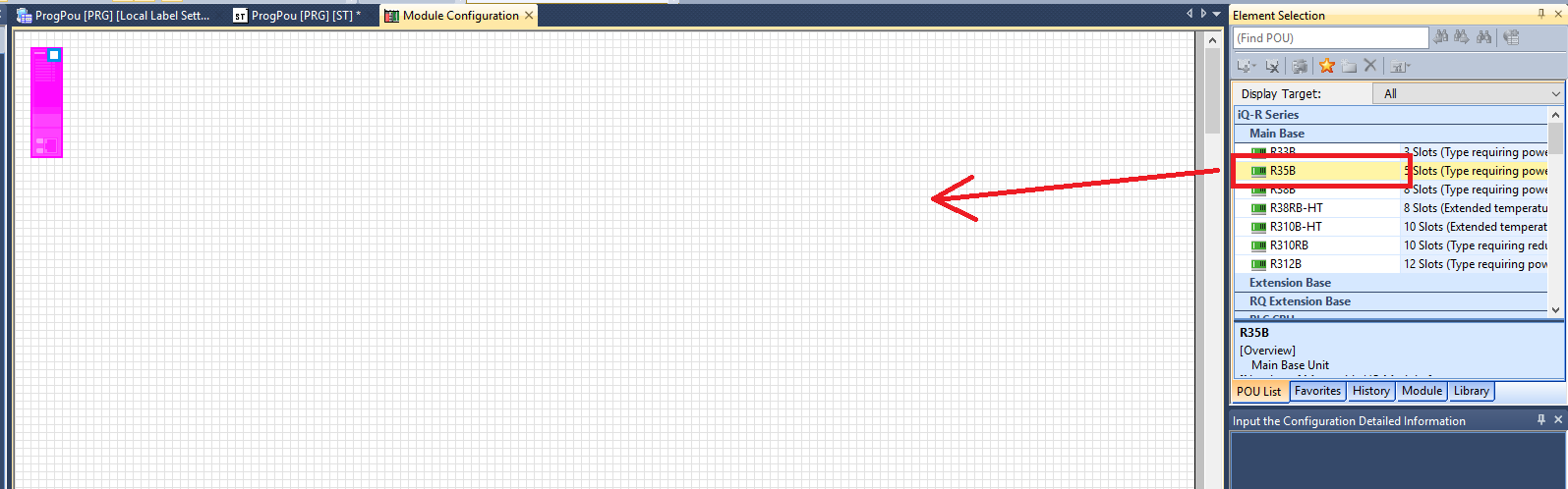
Step 5: Drag and drop the backplane unit you are using
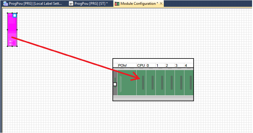
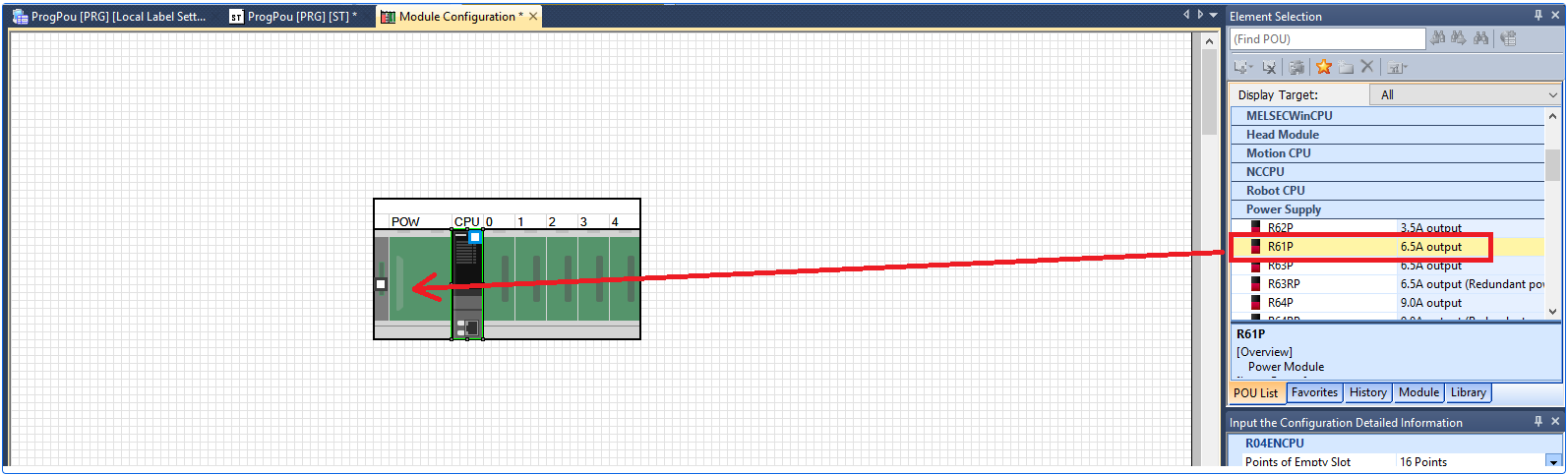
Step 6: Drag the CPU unit onto the CPU slot in the backplane. Drag and drop the power supply you are using onto the POW slot in the backplane
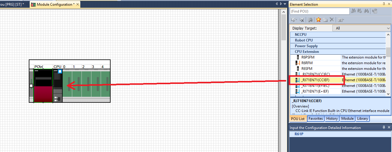
Step 7: Only if you are using a CPU module with a built in CC-Link module. Drag and drop the _RJ71EN71(CCIEF) CPU extension unit into the expansion slot next to the CPU slot
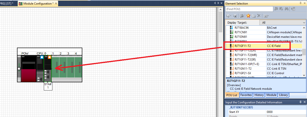
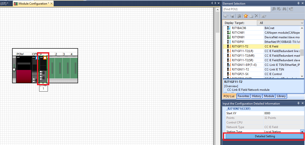
Step 8: If you are using a CPU with an external CC-Link module drag and drop the RJ71GF11-T2 module onto its slot on the backplane
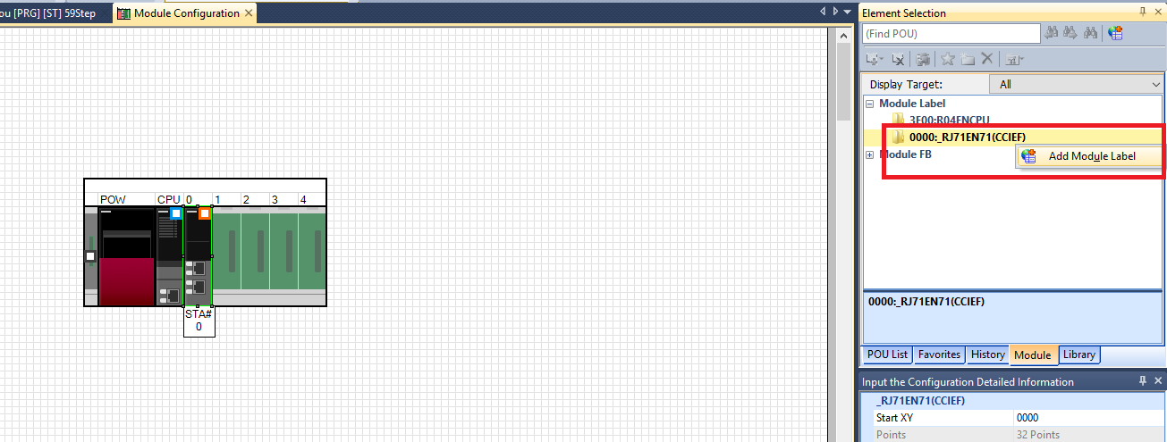
Step 9: In the Module tab of the Element Selection window right click Module Label -> _RJ71EN71 and click Add Module Label
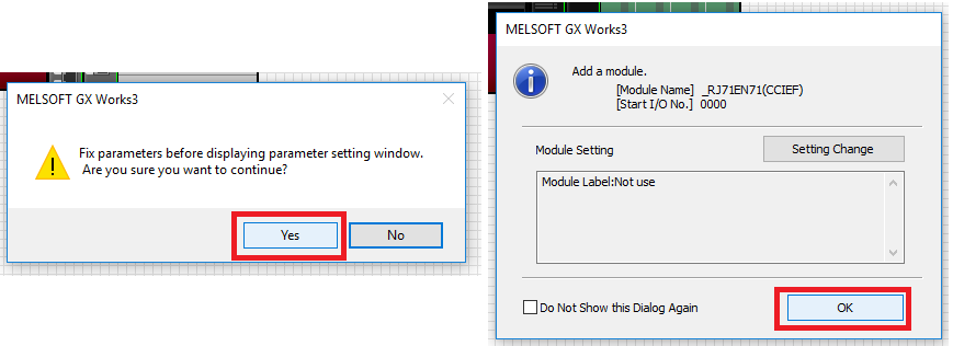
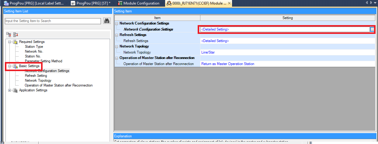
Step 10: Click the CC-Link module and click on Detailed Setting. Click Yes and OK in the confirmation windows
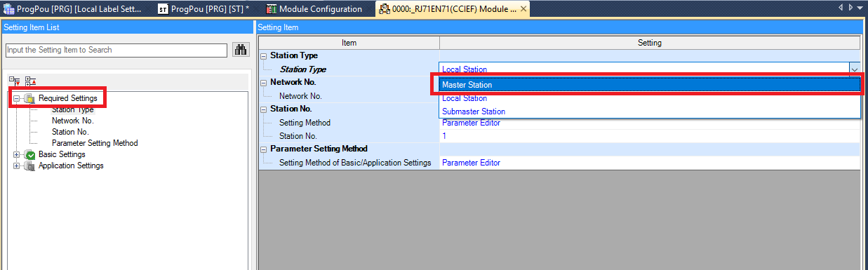
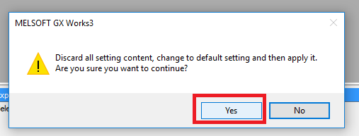
Step 11: In the RJ71EN71 module settings window go to Required Settings and switch the Station Type to Master Station. Then click Yes in the confirmation pop up
Step 12: Go to Basic Settings and double click Network Configuration Settings
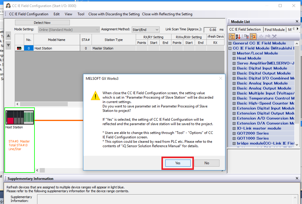
Step 13: Click Yes in the pop-up
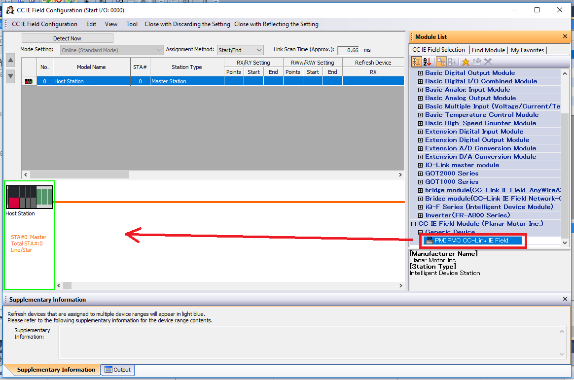
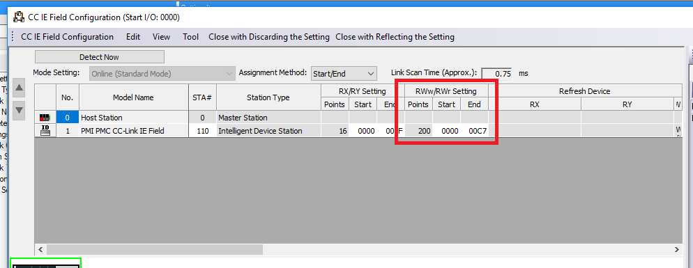
Step 14: In the CC IE Filed Configuration window scroll down the Module List and click CC IE Filed Module (Planar Motor Inc.)->Generic Device->PMI PMC CC-Link IE Field. Drag and drop it into the setup
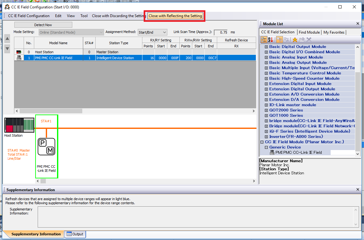
Step 15: Then click Close with Reflecting the Setting
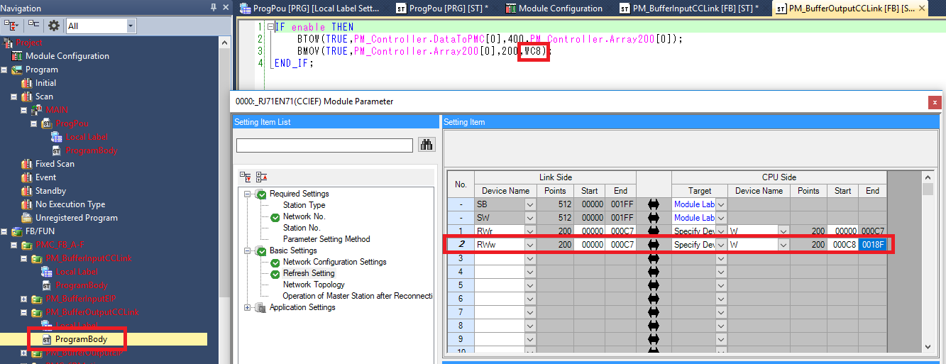
Step 16: In the RJ71EN71 module settings window go to Basic Settings and click on Refresh Settings
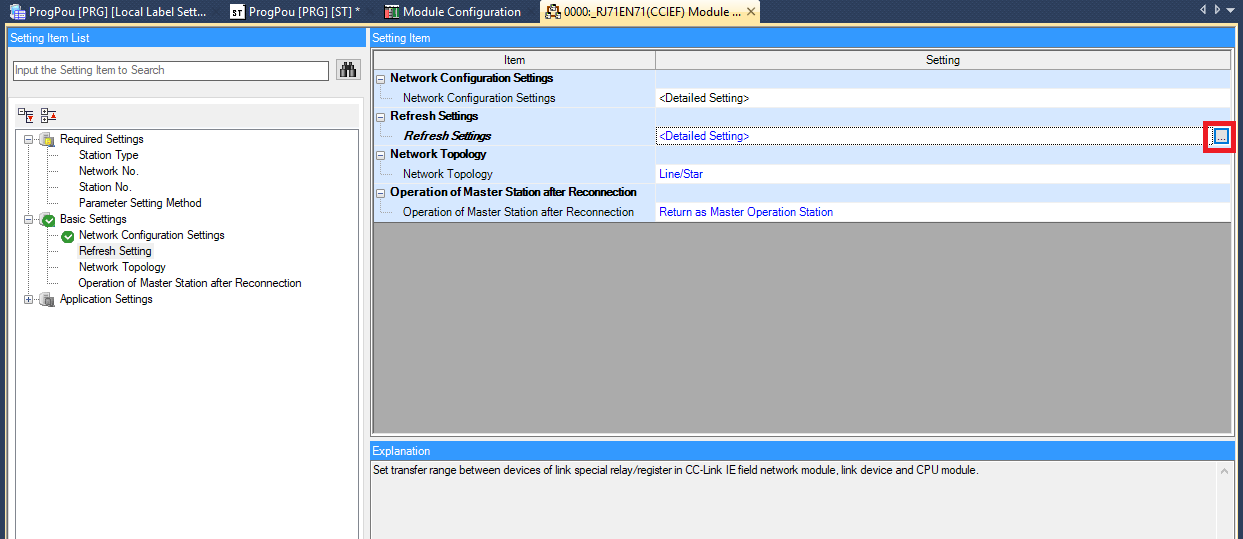
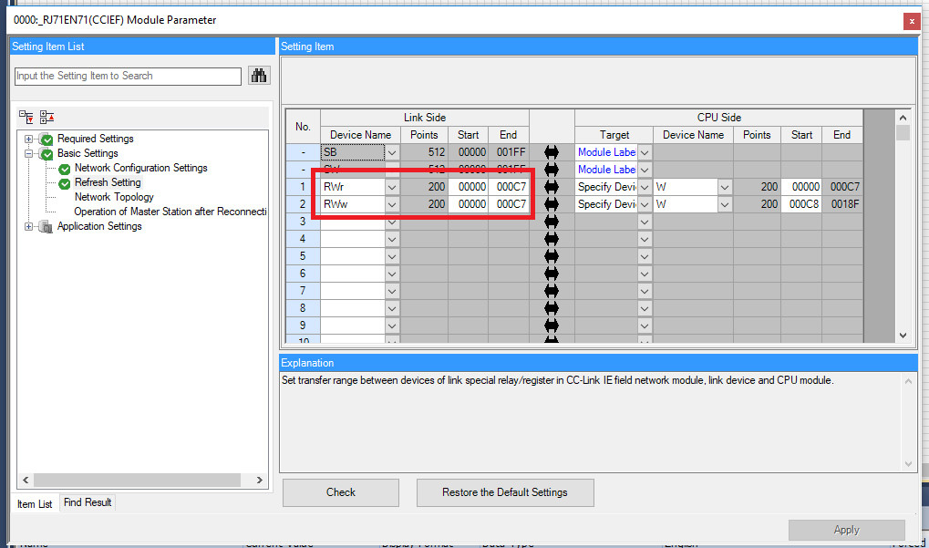
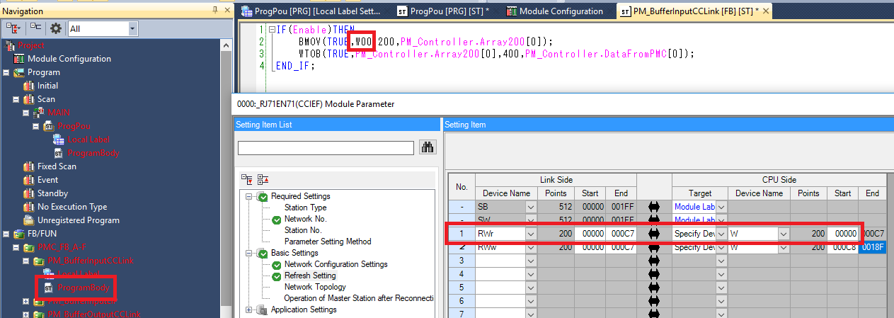
Step 17: In the Refresh Setting window create two 200 word links link above. Make sure that the Link Side matches the RWw/RWr settings match and that the CPU Side doesn’t overlap
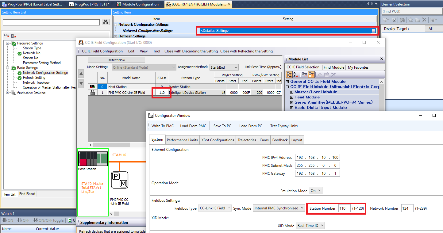
Step 18: Make sure that the Network No. set in GX Works 3 matches the Network Number set in the Planar Motor Tool Configurator
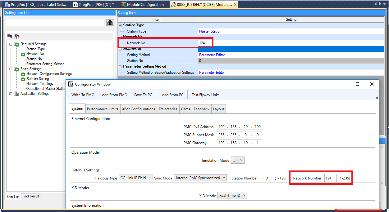
Step 19: Make sure that the Sta# set for the PMC in GX Works 3 matches the Station Number set in the Planar Motor Tool configurator
Import and use library
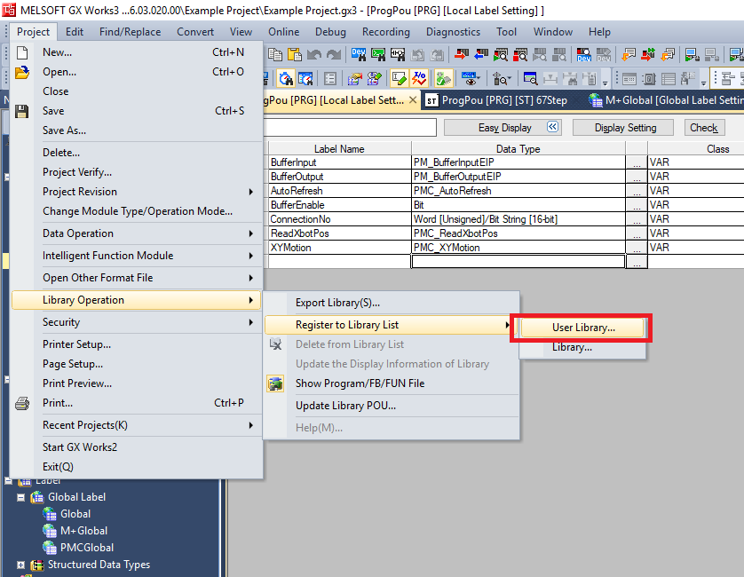
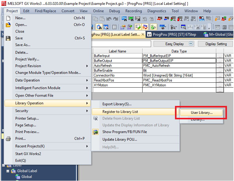
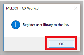
Step 1: Click Project -> Library Operation -> Register to Library List -> User Library. Then click OK in the pop up window
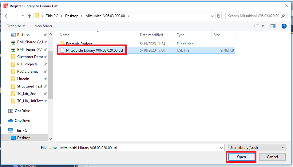
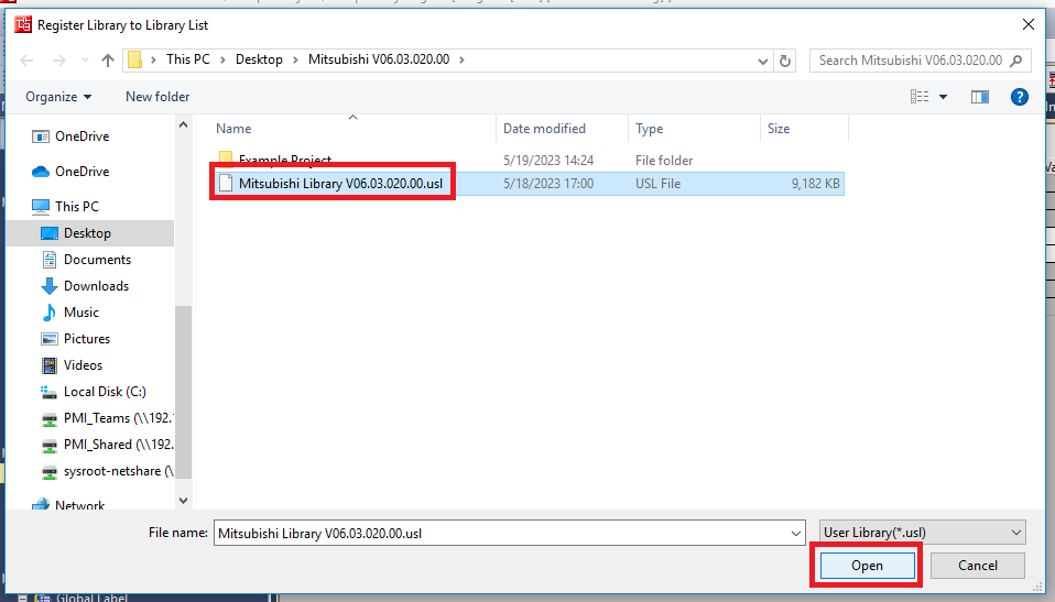
Step 2: Navigate to and select the PMC Mitsubishi Library .usl file. Click Open
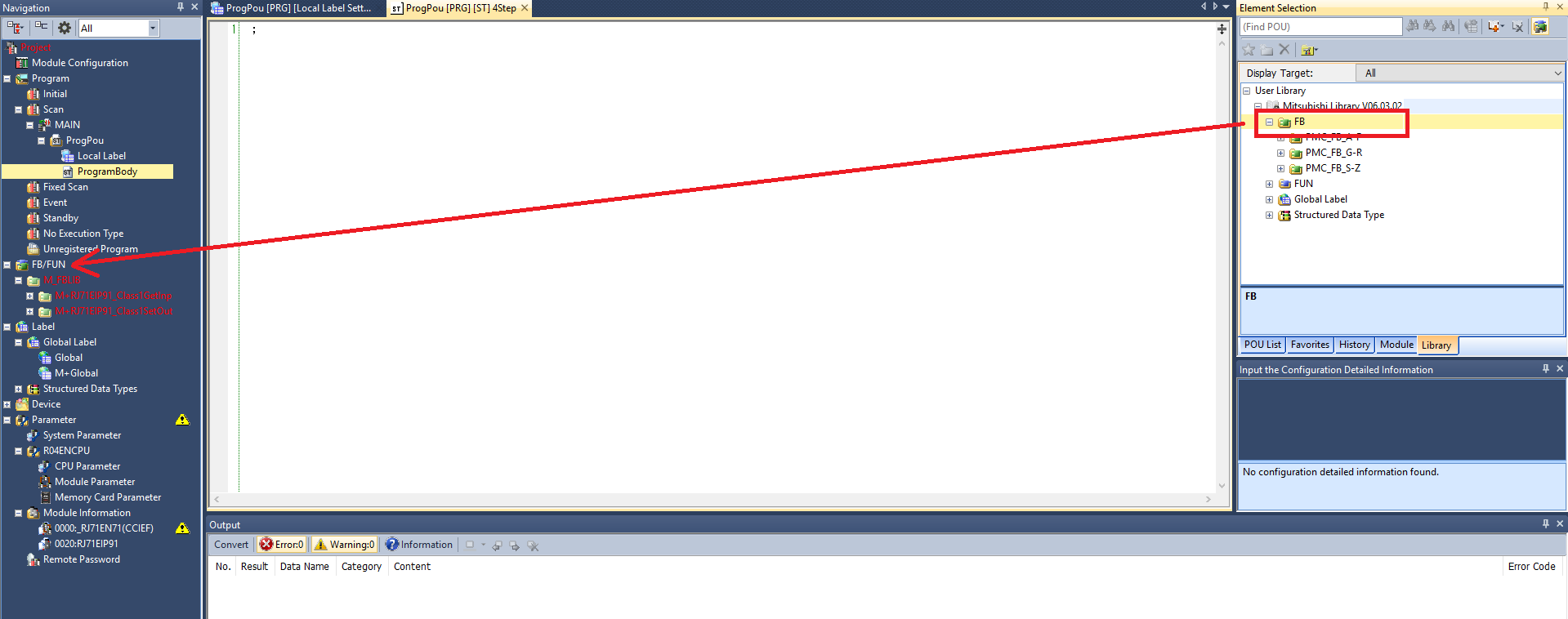
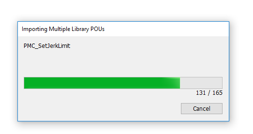
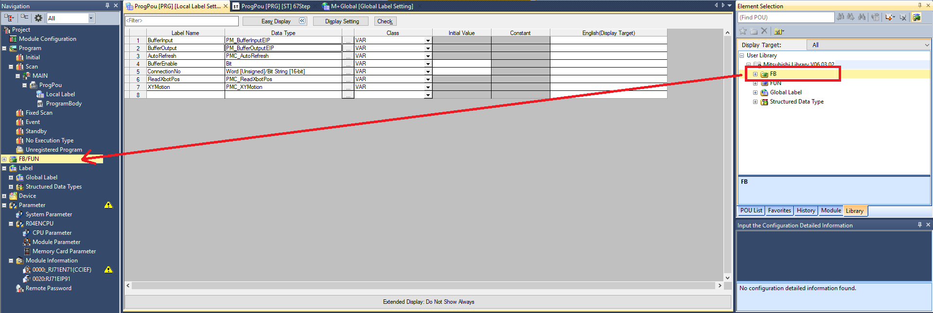
Step 3: In the Element Selection panel select the Library tab. Expand User Library -> Mitsubishi Library. Drag and drop the FB folder into the FB/FUN folder in the Navigation panel. This will automatically import over all the FBs, FUNs, Global Labels, and Data Types. The import progress will take multiple minutes
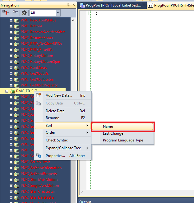
Step 4: It is recommended to sort the imported function block folders by Name since the import progress sorts them by last change
Step 5: Open the ProgramBody of PM_BufferInputCCLink and make sure that the src of the BMOV matches the CPU Side of the RWr defined for the PMC module
Step 6: Open the ProgramBody of PM_BufferOutputCCLink and make sure that the dest of the BMOV matches the CPU Side of the RWw defined for the PMC module
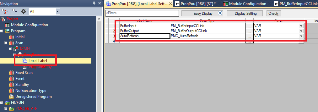
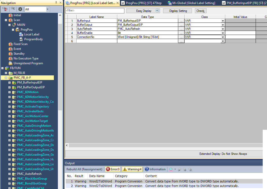
Step 7: In the Local Label of ProgPou declare one each of PM_BufferInputCCLink, PM_BufferOutputCCLink, and PMC_AutoRefresh function block variables
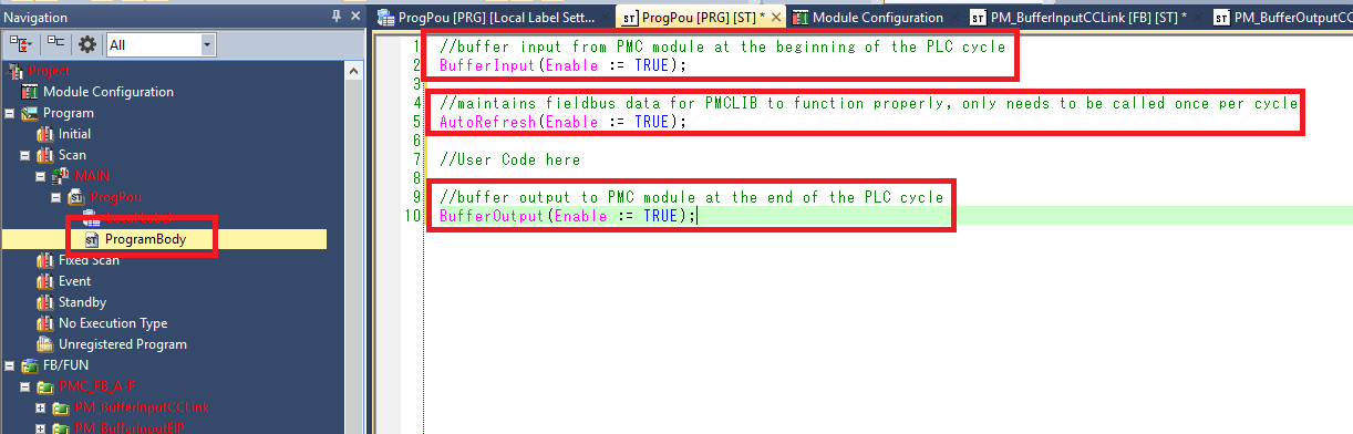
Step 8: In the ProgPou ProgramBody make sure the following is done:
-
Call the PM_BufferInputCCLink function block once at the beginning of the PLC cycle
-
Call the PMC_AutoRefresh function block once and only once per PLC cycle. Make sure that the AutoRefresh call is after the BufferInput call and before the BufferOutput call.
-
Call the PM_BufferOutputCCLink function block once at the end of the PLC cycle
Step 9: If you encounter the following error message when trying to write a converted project to the controller
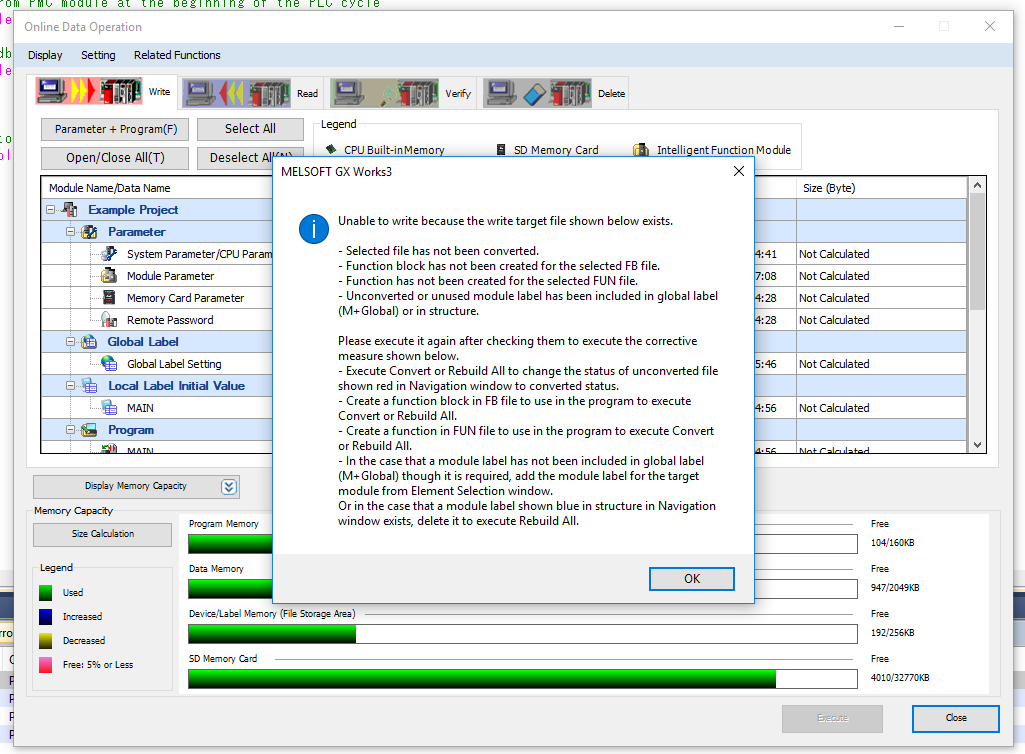
Step 10: It is because you have a FB/FUN folder that is not used in the project. For example, here I am only using blocks from the PMC_FB_A-F, and PMC_FUN folders (AutoRefresh uses blocks from PMC_FUN). So the error is because I am not using anything from PMC_FB_G-R and PMC_FB_S-Z folders
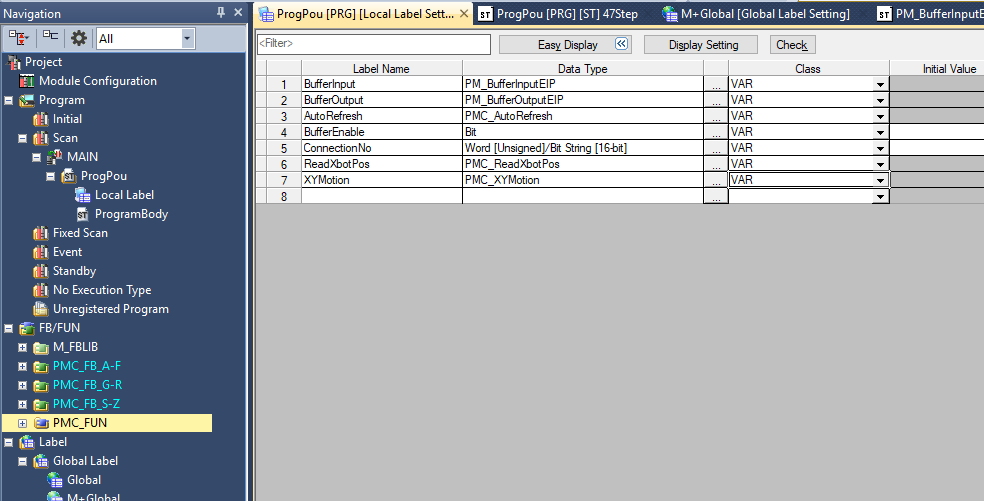
Step 11: You can correct this error by either deleting the unused folders or by using items from the unused folders. Here I have added PMC_ReadXbotPos from G-R and PMC_XYMotion from S-Z. This resolved the error and I was able to write the project to the PLC
Upgrade Library
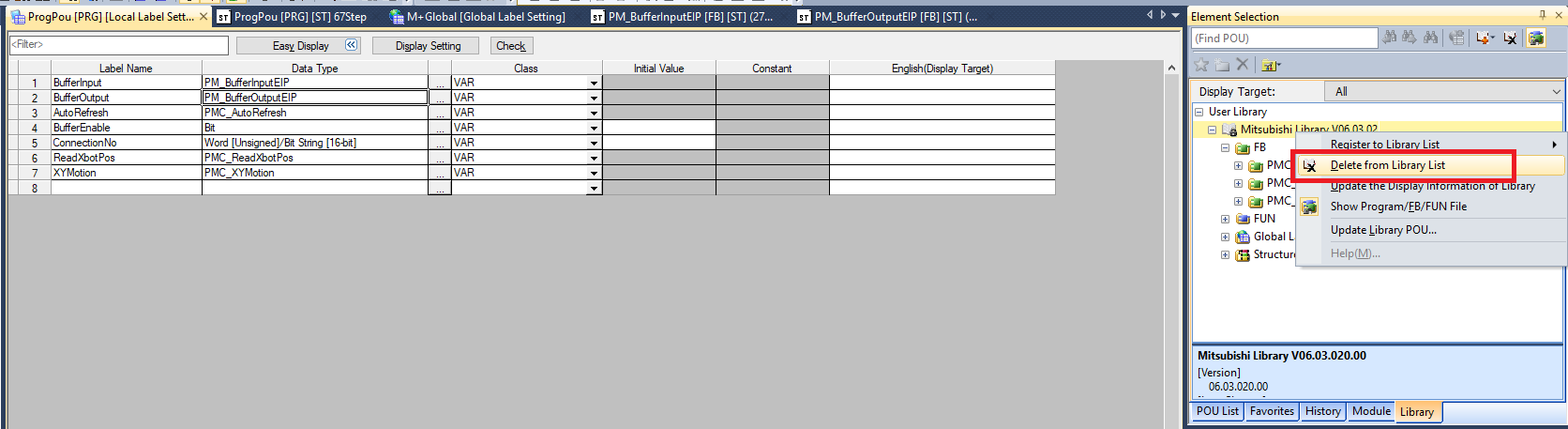
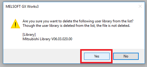
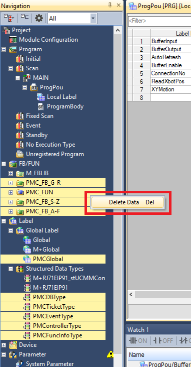
Step 1: In the Library tab of the Element Selection window Right click the old PMC Library folder and select Delete from Library List. Click Yes in the confirmation window
Step 2: Delete all the PMC FB/FUN folders, the PMCGlobal Global Label file, and all the PMC structured data types
Step 3: Click Project -> Library Operation -> Register to Library List -> User Library. Click OK
Step 4: Navigate to and select the new PMC library .usl file. Then click Open
Step 5: In the Element Selection panel select the Library tab. Expand User Library->Mitsubishi Library. Drag and drop the FB folder into the FB/FUN folder in the Navigation panel. This will automatically import over all the FBs, FUNs, Global Labels, and Data Types. The import progress will take multiple minutes
File I/O on the PLC (Optional)
The following is one possible way to read and write files to the PLC storage. It could be helpful for commands such as Set PMC Configuration.
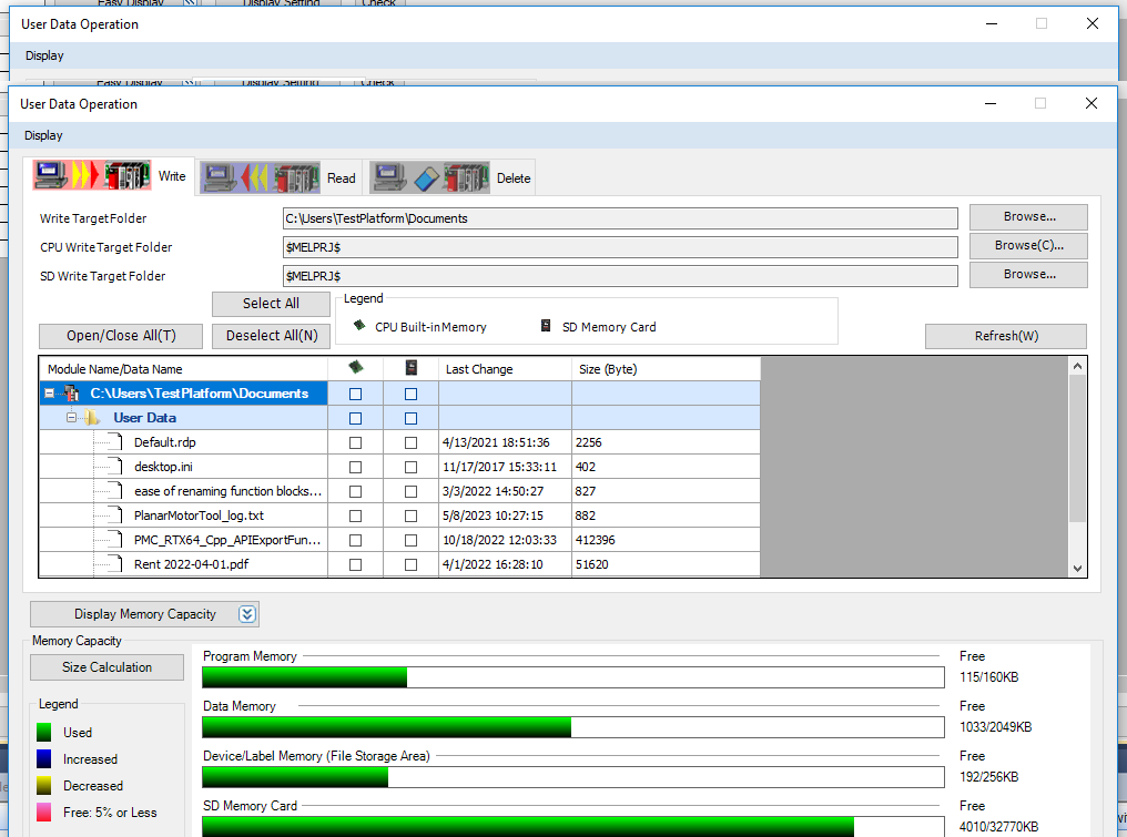
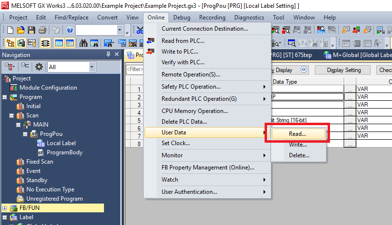
Step 1: Click Online -> User Data -> Read/Write/Delete
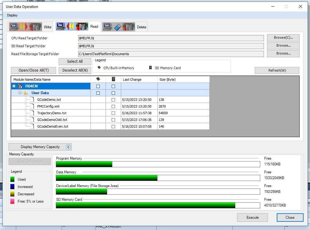
Step 2: In the Read tab you can select which files on the controller you wish to download to the computer. Read FileStorage TargetFolder is the directory where the selected files will be saved
Step 3: In the Write tab you can select which files on the computer you wish to download to the controller. WriteTargetFolder is the directory on the computer from which you can select the files to load onto the controller