
Maximum Pressure
Flyway maximum permissible coolant pressure is 340 kPa (50 PSI).
Many commonly available 10mm tubing options are only rated to 275 kPa (40 PSI) or lower. Failure to observe pressure ratings of selected tubing may result in personal injury or damage to property caused by rupture and rapid decompression of coolant lines.
Flow Coefficient and Steady State Temperature
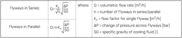
The Flyway flow factor, Kv, has been experimentally measured at approximately 0.42 m3/h for 3-Series and 0.44 m3/h for 4-Series.
An estimate of the system’s flow rate can be calculated using the pressure drop across the Flyways and the flow factor, Kv, for each Flyway as follows:
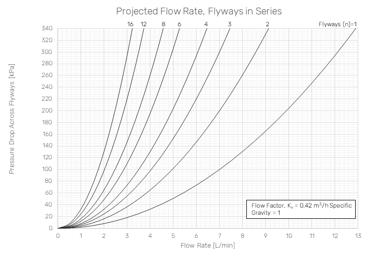
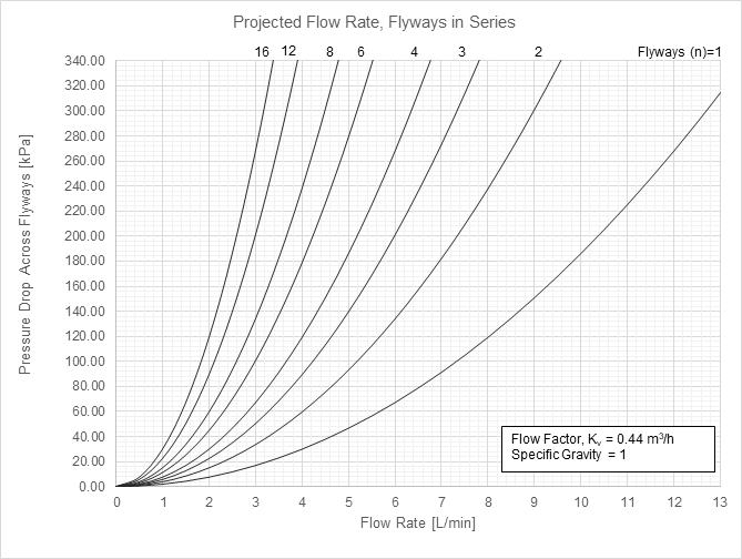
The following charts provide the projected flow rate through 3-Series and 4-Series Flyways connected in series for various pressure drop across the Flyway systems. These charts are only a projected flow rate, actual flow rate may vary depending on other components in line with your system and your specific pump’s capacity. For parallel cooling layouts, the projected flow rate can be estimated by multiplying the projected flowrate of each branch by the number of branches, assuming that each branch of the parallel layout contains the same number of Flyways.
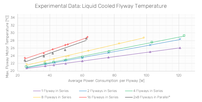
The experimentally collected data in the graph below shows the measured steady-state temperature for different numbers of 3-Series Flyways in series with a small water chiller, with a least-squares best fit line applied. This data can provide a benchmark for system integrators when designing their cooling system. The chiller specifications and cooling liquid flowrate information is shown in the tables below. For the 16 Flyways in series and 8x2 Flyways in parallel test cases, the experimental chiller’s cooling capacity was saturated for power consumptions greater than 65 W per Flyway. If lower temperatures are required for the application parallel routing, increased liquid flowrates, and/or cooler input temperature should be implemented.
|
Experimental Conditions |
|||
|
Water Chiller Data |
|||
|
Nominal Cooling Capacity |
1700 W |
||
|
Pump Power |
48 W |
||
|
Compressor Power |
0.75 kW |
||
|
Maximum Flow |
16 L/min |
||
|
Ambient Temperature |
21 ⁰C |
||
|
Cooling Liquid |
Distilled water |
||
|
Test Case |
Liquid Flowrate [L/m] |
Pressure Drop Across Flyways [kPa] |
Liquid Input Temperature [°C] |
|
1 Flyway in Series |
5.0 |
74 |
18.5 |
|
2 Flyways in Series |
4.4 |
92 |
18.5 |
|
4 Flyways in Series |
3.7 |
112 |
18.6 |
|
8 Flyways in Series |
2.8 |
126 |
19.1 |
|
16 Flyways in Series |
2.1 |
147 |
19.5 |
|
2x8 Flyways in Parallel |
3.8 (Total) |
109 |
20.7 |
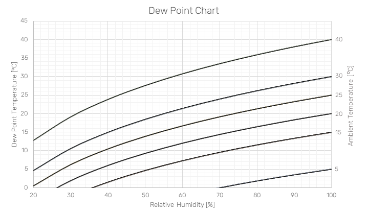
Condensation may occur on a cooled system if the system's surface temperature is below the dew point temperature of the air around the system. The dew point temperature depends on the humidity and ambient temperature and can be determined using the following chart. For example, for an ambient temperature of 20°C and a relative humidity of 70%, the dew point temperature is approximately, 14°C. The input temperature of the cooling liquid should therefore be set higher than 14°C to remove the chance of condensation. Consider dehumidifying the ambient air to eliminate condensation.
Thermal Load Estimation
The thermal load of a system can be estimated using either of the following methods:
-
Compute from maximum rated capacity of system’s power supply(s)
-
The average power consumption of a Planar Motor system typically does not exceed half the rated power of the system’s AC/DC power supplies
-
Assume required cooling capacity is approximately equal to average power consumption
-
-
Compute from experimental results
-
Use the “Get Flyway Status” function in Planar Motor Tool to obtain instantaneous Flyway power consumption of any given Flyway in the system
-
Record instantaneous power consumption of all Flyways during typical operation. Estimate required cooling capacity as equal to the cumulative instantaneous power consumption of all Flyways
-
For both methods, note that the chiller should have a maximum cooling capacity sufficiently above the actual thermal load of the system. If the thermal load approaches the chillers’ maximum capacity, an unacceptably high coolant temperature rise may occur. Choose a chiller with an oversized cooling capacity to avoid this problem.
Flyway Cooling Channel Capacities
When calculating the total coolant volume required for the system reservoir and expansion tanks, the internal volume of the Flyway cooling channels must be aggregated. The following table provides the nominal internal capacities for the flyway models.
|
Flyway Model |
Internal Cooling Volume |
|
S3-AS |
33 mL |
|
S3-AN |
31 mL |
|
S4-AS |
61 mL |
|
S4-AN |
77 mL |
Note: These values represent the internal volume of the Flyways only. For a complete system calculation, the cumulative volume of all external tubing, manifolds, and the chiller unit must be accounted for to ensure sufficient fluid capacity and pressure stability.